VEMS v3.3 installation instructions
When planning, usually best to start from the
- [product options]
- and for settings see VemsTune and [VT help] as the primary source of info
- notably [wire userguide]
- an old [pdf version here] (not maintained, but the main concept hasn't ever changed)
OBSOLETE old version ...
These instructions are written for a typical Windows Installation. It is assumed that the reader is well versed with fuel injection theory and has a working knowledge of the electronics that make up an engine management system i.e. the sensor types, fuel injector impedences and ignition types.
Engine management systems give you the control you need to get the best from your engine, but they have a huge potential for damage, both of your engine and you and your property. This potential is lessened if you follow some simple rules.
- You MUST have a fire extingusher on hand
- Correct Power connection is ESSENTIAL read then re-read the information in Step One, failure to connect the grounds properly will damage your unit
- The most important sensor is the primary trigger (crank sensor or distributor trigger), get this working first.
- Ensure that you understand the correct methods for grounding.
- Connect and test the sensors before you consider connecting injectors, fuel pump relays etc.
- Ensure that you understand the correct methods for grounding.
- When testing your connectors you will often need to turn the engine on the starter motor, remove your spark plugs to reduce the load on the starter, don't run the starter for too long, keep an eye on the temperature of the starter motor, battery and starter motor cable, these can get hot and overloaded.
- Ensure that you understand the correct methods for grounding.
- Connect your ignition components first, follow the steps in the Configuring Ignition section.
- Ensure that you understand the correct methods for grounding.
- Start with conservative maps, tuning is an itterative process, your first task will be to get the engine to idle, then to hold rpm without load.
- Ensure that you understand the correct methods for grounding.
- Finally, remember that this is always going to be a learning experience, and that it should be fun! Oh, and check your grounds are correct.
It is important to follow the guide in the defined steps, failure to do this may result in you frying your VEMS module.
The EC36 is the larger Econoseal 36pin plug, and EC18 is the smaller Econoseal plug.
In-car installation
Although VEMS has good environmental protection the engine bay of a car is still a very hostile place to install your VEMS module, so its a good idea to follow the lead of most car manufacturers and keep the ECU inside the passenger compartment.
Setting up your PC
The easiest way to configure and tune your VEMS unit is to use a PC, the first step is to install the tuning software.
VemsTune package, the latest version of which can be obtained from: http://www.vems.hu/vt
Step One - Connecting power & testing
IMPORTANT Read these instructions carefully, correct and proper grounding of your VEMS unit is essential for its life and successful operation. If you fail to connect your unit correctly you will AT BEST damage it.
Grounds
From the outset it cannot be stressed enough just how important grounding is. 95% of all noise issues are due to poor grounding.
Grounds are connected strong, but near the ECU. There are two branches so the fluctuation of power signals do not interfere with the measured signals (most importantly: the trigger):
Power Ground handles the noisy and high currents generated by driving injectors, coils and solenoids.
Sensor Ground handles 0 to 5v signals from crank, throttle and temperature sensors. VR-trigger sensor at low RPM (cranking) is the most sensitive to noise.
The GROUND rules:
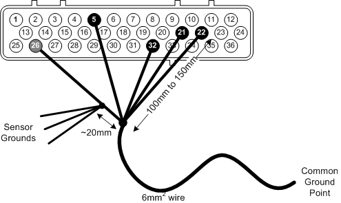
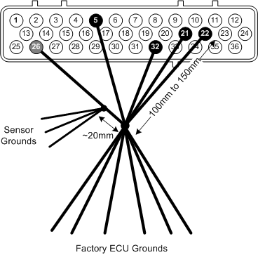
- connect GND and the 4 GND5 with short (preferrably 10..15cm, max 20..30cm from EC36), stong (preferrably 0.75mm2 or stronger) wires.
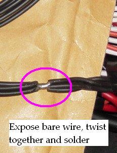
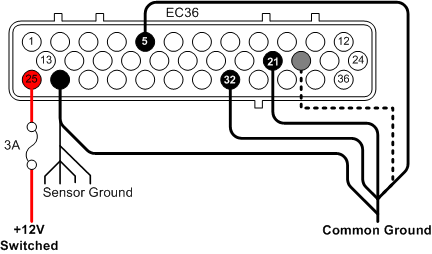
- Power Grounds & Sensor Grounds MUST terminate at the same point - Common Ground. Run the wires into a single ring crimp so that there is no chance of one ground coming free.
- Keep the Power Ground connection (EC36 pin26, 5,21,22,32) pins to the Common Ground point short max 0.1 .. 0.3m,
- use strong wires. Preferrably all 5 wires should be 0.75mm2 or stronger. Some installations (particularly with no PWM-ing) could tolerate somewhat longer wires, but why risk it ? (ground problems are like ghosts, very hard to track down). The length of wire(s) from this common ground point to battery / chasses can be longer (and usually are long). Strong wires must be preferred (total 4mm2), and not longer than necessary. But at least nowhere near as sensitive as the wires right at the ECU.
- connect the ground of the sensors to the Common Ground point or to the sensor ground branch, that is EC36pin26.
- Connect Power Grounds to the Common Ground point, or anywhere you like (except the sensor-ground branch)
- Failure to connect Sensor Ground and Power Ground will damage your VEMS. Even on the test bench !
Power Grounds
Also called as "GND5" in some documents
- EC36-pin5 to Common Ground
- EC36-pin21 to Common Ground
- EC36-pin32 to Common Ground
- EC36-pin22 to Common Ground
Sensor Ground
- EC36-pin26 to Common Ground. NOTE: Sensor Ground pin has many connections (CAS, TPS, IAT, CLT ...) make provision for this in your wiring loom.
Common Ground
The engine block is the best point from many perspectives. But it is of some importance to keep this ground point away from the alternator and starter ground paths, you can do this but adding extra grounding wire at the alternator to ensure a path of low resistance.
Having the ground path for the alternator, starter and the ecu at the same point is not a good idea. So keep the ECU connection to the block as far away as possible.
- If the alternator is bolted to the engine block you way want to ground the ECU to the head
- If the alternator is bolted to the cylinder head you may want to ground the ECU through the engine block, well away from the ground strap.
- On engines like those fitted to some Audis (Where the alternator is bolted to the head) it is acceptable to bolt the ECU earth to the far side of the cylinder head.
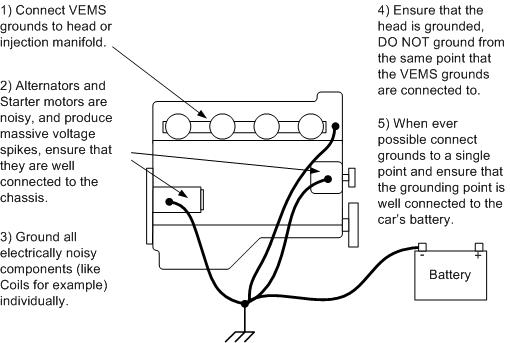
Your ecu will always share some of the groundpath with the alternator. You want to make sure that the shared path is as short as possible and that it is as low resistance as possible.
Grounding directly at the battery is not a good idea, at the negative of the battery you always see the current pulsations from the alternator and starter, the big currents flow from battery to starter and alternator to battery, although you may hope that the battery may act as a buffer, lead batteries are pretty slow and it doesn't filter the noise very well.
The placement of the battery also change a lot of things, if you have a battery located in the boot you could need upto five 4m wires. Also And the connection at battery connectors is often forgotten by techs, are subject to aggressive corrosion, abused when connecting jump leads.
Connecting to the chassis is often a bad idea, the body of the car is an inferno of ground currents. For example the wipers, electric seats (consuming 50A+ when operated) etc may be grounded at the same point as the ECU. And voltage fluctuations are are higher as you get further from the battery.
+12V Supply
- EC36-pin25 3A Fused +12v supply
Once you have connected and checked the continuity of ground you can connect your VEMS unit to the EC36 plug and apply the power supply. There is little point in connecting power until the serial connector or LCD screen has been connected.
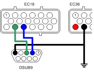
Connecting serial port
To allow the connection of the VEMS unit to your PC a serial port plug must be connected as follows.
- EC18-pin14 to DSUB9-pin3
- EC18-pin15 to DSUB9-pin2
- EC36-pin26 to DSUB9-pin5 (GND).
Testing the VEMS unit
First connect your VEMS serial cable (see Step Two), and make sure that there are no applications that use the serial port running on your PC, applications such as Palm Pilot HotSync.
Connect the EC-18 connector with the serial port to VEMS.
And then connect the EC-36 connector with the power supply.
Download and start VemsTune, and see [vemstune tutorial videos and help].
This page has some "MegaTune" reference and screenshots. MegaTune is the old (very old) tuning application, superceeded by VemsTune a long time ago. You'll find similar (just better, nicer and more) dialogs in VemsTune. In short, forget megatune and always use VemsTune (which is newer, uptodate, better, nicer and more complete, supports easier firmware upgrade, warns for many suspicious - likely unintended - settings, and supports the CRC-protected communication, which is the only way to go).

Select the VEMS Standard 12x12 (Default) option and click OK.

On the Menu bar select Communications->Settings...

Select the com port that VEMS is connected to, and click the 'Click to test' button, if all is well you will see the success message

This shows that your VEMS module is alive and communicating with the PC, close the Settings window and you should see something similar to this:

Close MegaTune and disconnect VEMS from its power supply.
Step Two - Connecting and configuring sensors
The trigger is the engine management system's most fundamental sensor, without one VEMS cannot calculate engine speed or crank angle. If you are connecting VEMS to an engine that has an existing engine management system, if not then a triggering method will need to be put in place.
The simplest type of trigger is to use the existing distributor to provide a pulse for each cylinder. This type of trigger is more than adiquate for driving ignition through a distributor and batch fire injection.
Connecting the primary trigger (CAS)
Magenetic sensor / Variable reluctance (VR)
Mechanical considerations (need to be written somewhere and referenced from here)
The VR sensing circuitry is very sensitive to electrical noise, shielded cable (coax) must be used and good grounding is vital.
- EC36-pin27 VR+ Note that some other ECUs trigger on positive-going edge so their schematic might mark the + and GND swapped: so don't blindly follow naming from autodata pinout or some schematic, keep in mind that + and - might need to be swapped. Measure to be sure: InputTrigger/TriggerLog
- EC36-pin26 VR-

Hall Sensor
VEMS is available configured for Hall sensors, these are more noise tollerant and require a +5V supply.
- EC36-pin27 Hall signal
- EC36-pin26 Ground
- EC36-pin28 +5V

Connecting the secondary sensor (optional)
Magenetic sensor / Variable reluctance (VR)
With the same considerations with the primary trigger regarding electrical noise.
- EC36-pin13 VR+ (central wire in coax)
- EC36-pin26 VR- (shield and ground)

Hall Sensor
- EC36-pin13 Hall Signal
- EC36-pin26 Ground
- EC36-pin28 +5V

Configuring the system to use the Crank sensor
Primary Trigger
Configuration is done through MegaTune menu option: Settings->Primary Trigger

Simple Trigger
In its simplest form your VEMS will trigger from a simple pulse per firing event which is called Coil Type trigger as the trigger signal usually comes from the distributor or coil. To select this type of trigger select 'Coil-type' from the Type dropdown list.
Multi-Tooth Trigger
Because of its highly flexible triggering system VEMS needs to be configured correctly, thankfully the complex task of seting up the system has been made a great deal easier with the utility here:
http://koabi.lazyslacker.com/VEMS/cranktriggers.php
Typical trigger settings...
Secondary Trigger (Cam Sync)
For fully sequential ignition/injection you will need to use the secondary trigger option. Configuration is done through the MegaTune menu option: Settings->Secondary trigger/Cam sync settings

Testing the crank sensor
Make sure that the fuel pump and injectors are not active by removing their fuses. Start MegaTune and leave it showing the main screen (with the guage display)
Temperature Sensors
VEMS uses two temperature sensors: Inlet Air Temperature which is used in speed/density systems to calculate the amount of fuel required. And Coolant Temperature which is used to meter the required amount of warm-up fuel enrichment.
Connecting the inlet air temp. sensor (IAT)
If you are using a VEMS MAP sensor please refer to the section titled Connecting an external MAP sensor
- EC36-pin2 Signal
- EC36-pin26 Ground

Connecting the coolant temp. sensor (CLT)
- EC36-pin14 Signal
- EC36-pin26 Ground

Configuring the temperature sensors
Use EasyTherm to build tables.
Upload tables.
Testing the temperature sensors
Using MegaTune.
Check ambient temperature with thermometer
Check sensors reading on MegaTune or Motuner, compare with thermometer.
Apply known heat (boiling water) and check reading.
Apply known cold (ice) and check reading.
Connecting the throttle position sensor (TPS)
The throttle position sensor is used by VEMS to provide fuel requirements in Alpha-N configuration and acceleration enrichment.
- EC36-pin29 TPS (+5v) out
- EC36-pin1 Wiper out (0-5v)
- EC36-pin26 Ground

Configuring and testing the TPS
Configuration is done using MegaTune Settings->Basic Settings

- Set TPS Low (ADC) value to 0
- Set TPS High (ADC) value to 255
Ensure that the throttle is fully closed by setting the idle adjustment screw to its minimum.
Before setting any values ensure that your accelerator pedal fully opens the throttle plate.
Now open the calibration screen Tools->CalibrateTPS...
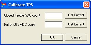
- With the throttle fully closed click the Get Current button next to the Closed throttle ADC count.
- With the throttle fully open click the Get Current button for the Full throttle ADC count.
If the full throttle value is smaller than the closed throttle value you will find that the TPS has been wired incorrectly and you may need to change the +5v and ground connections around.
[dnb]The TPS must be configured accurately, especially at the lower end of pedal travel, otherwise deceleration fuel cut may not work correctly, resulting in lurching behaviour. If the fully closed calibration value you found is 0, then you need to adjust the throttle position sensor on the throttle spindle such that the calibration value is 1 or more.
Likewise, the calibration value for full throttle should be less than 255 if this is possible given the above constraint.[/dnb]
Make a note of the numbers and return to the Settings->Basic Settings screen and set the Low and High TPS values accordingly.
On the main screen check that the pedal movement is reflected correctly in the TPS gauge.
Finally turn the idle adjustment screw to open the throttle plate slightly. You will need to fine adjust it later.
Setting TPS High
With the throttle fully open adjust the TPS High (ADC) value until the TPS reads 100%.
Connecting manifold air pressure (MAP) sensor
In early versions the MAP sensor is built in to the VEMS module. In order to ease installation it is suggested that an external sensor such as the VEMS 250kpa or high boost (over 18psi) 400kpa sensor, or the OEM sensor be used.
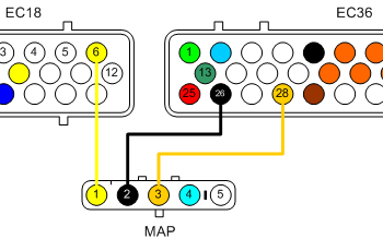
Connecting an external MAP sensor
VEMS MAP sensors come in either 5V or 12V supply options, the pin outs of which are:
5Volt, 250kPa Sensor
- MAP-pin1 MAP out (0 to 4.8V)
- MAP-pin2 GND
- MAP-pin3 5V Supply
- MAP-pin4 Not connect
- MAP-pin5 Not connected
5Volt, 400kPa Sensor
- MAP-pin1 MAP out (0 to 4.8V)
- MAP-pin2 GND
- MAP-pin3 5V Supply
- MAP-pin4 Board temp. out Not IAT
- MAP-pin5 Not connected
Connections to VEMS will be:
- EC18-pin6 to MAP-pin1
- EC36-pin26 to MAP-pin2
- EC36-pin28 to MAP-pin3
Connecting the internal (old style) MAP sensor
To connect the internal MAP you will need to route some 6 or 8mm tubing from the manifold to the VEMS module. It is advisable to use copper brake pipe for long pipe runs especially near heat in the engine bay.
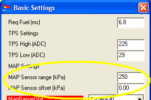
Configuring and Testing the MAP sensor
Using MegaTune Settings->Basic Settings
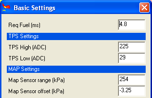
Setting Map sensor range
Map sensor range is set to the maximum kpa value of your MAP sensor, if you are using the VEMS sensors this is either 250 or 400, for other sensors you will need to refer to the manufacturer for the sensor's maximum range.
Setting Map sensor offset
Consult your local weather for the current air pressure, this tends to range from 995 to 1028 or there abouts. Adjust the Map sensor offset value until the MAP reading reflects the current air pressure (typically between 99kpa and 103kpa).
Connecting Mass Air Flow (MAF) Sensor
VEMS can use a MAF signal to meter the engine load. Configuration of MAF is detailed in the section Configuring Air Metering
Connections to VEMS will be:
- EC18-pin6 to MAF's Signal
- EC36-pin26 to MAF's Ground
- EC36-pin28 to MAF's 5v in
Configuration
Configuring a MAF is not a trivial task, and may need to be done on a running engine. The Range of the MAF signal will be configured with the MAP Sensor range (kPa) value, and calibrated using MAP Sensor offset (kPa)
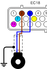
Connecting WBO2 Sensor
- EC18-pin13 to WB6-pin1 (Nerst Cell Signal)
- EC18-pin7 to WB6-pin5 (WBO2 Pump-)
- EC18-pin18 to WB6-pin4 (WBO2 Heater)
- EC18-pin9 to WB6-pin6 (WBO2 Pump+)
Before we actually plug the wideband in we need to do some tests and calibration.
Calibrating the WB02 controller circuit
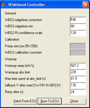
The first step is to ensure that we have the Factory recommended Wideband settings, these are
Settings->Wideband Settings
Settings->Wideband Controller PID
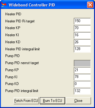
You will see that Pump zero pw (5V/256), Pump PID nernst target, and WBO2 calibration constant are greyed out, these are specific to your VEMS unit and sensor.
For pre-built units Pump zero pw (5V/256) and Pump PID nernst target values are provided when the unit is sent out.
If you bought an assembled VEMS you can skip to the Calibrating the WB02 sensor section.
Pump zero pw (5V/256)
The first check is 'Pump Zero DC', so you will need to take a reading with a DVM across pins 5&6 of the Wideband connector. The ideal voltage is zero.
wbo2_pump_pw_zero value is adjusted during factory test, saved in ECM eeprom. Don't forget to save the the current settings by saving the output of the terminal command Manmcd or use download-config.bat before making any calibration changes.
To adjust the voltage you will need to use the terminal program to change the value directly. To do this use the command: Mang8Ac63mcs And you will make adjusments starting from 63 upwards.
The wbo2_pump_pw_zero value is likely between 0x63 to 0x66 (99 .. 102 decimal as adjusted in MegaTune 'Pump Zero DC'). Example:
- at wbo2_pump_pw_zero=0x65 I measured 0.10v
- changing to wbo2_pump_pw_zero=0x64 resulted in a reading of -0.17
- and 0x66 took the reading up to 0.4v.
Note that WBO2 must be restarted for the value to take effect (reboot the board).
Pump PID nernst target
Once you are satisfied that wbo2_pump_pw_zero is as close to 0v as it can be, you should verify the pump and nernst control voltages. You'll need two 100 Ohm resistors. Power down the board then
- insert one 100 ohm resistor between wbo2_pin1 and wbo2_pin6
- and the other 100 ohm resistor between wbo2_pin1 and wbo2_pin5.
- Power up the board, and switch to LCD page 2 using the command Manmlp02 and display the page with the command mll
- Enable the WBO2 heater with mde02, and wait for the O2% to be displayed by refreshing the display with mll.
Just to verify, check that the voltage between ground and wbo2_pin5 (nernst-) reads appr 4V. 3.9V .. 4.1V is perfect. Note that this cannot be change in configuration or firmware, it's controlled by hardware. If less than 3.8V or above 4.2V, there is good chance the wiring is bad, check it.
Using a DVM, check that voltage between wbo2_pin1 and wbo2_pin5 reads appr 0.45V (0.44V or 0.46V is just as good). If it's slightly out, you can adjust the value by typing: Manmttg89c85mcs and adjusting the value 85
As before, you'll have restart the board between any config value changes, remember to change to page 2, start the heater and wait for an O2% display (Manmlp02, mde02, mll)
If you cannot get close to this 0.45V target, check the values wbo2_pump_pid ... for example wbo2_pump_pid_ki and wbo2_pump_pid_ilimit, against a known good config. Finally, verify with the DVM that the difference is 0.45V.
- Send mde00 to turn off the WBO2 heater.
Calibrating the WB02 sensor
Now that the controller is calibrated, you can connect the sensor and calibrate it against fresh air. Ensure that the sensor body is grounded, and power up the board.
Now start up the built-in mini-terminal in the communications menu of MegaTune.
Our first task is to set VEMS to print the correct information page when requested, to do this type:
Manmlp02
Typing {mll will show the information displayed on the selected page, you will see that O2% is displayed as ??.? And that the Heater is Off.\n
RPM:0000 W00I00 P099
0000 00, 0000 66
00 F1 00 00 0DF7
AFR=?     O2%=??.?
The Wideband needs to be upto temperature in order to operate, so we need to turn the heater on with the command:
Manmde02
It will take 30-60 seconds for the wideband to get to temperature, you can type mll To check the progress of the heater.
Once the heater is up to temperature the O2% reading will display a value rather than question marks. We now need to adjust the calibration value so that the O2% reading is correct. The earths atmosphere is 20.9% Oxygen, we'll settle for a figure close to that.\n
RPM:0000 W00I00 P099
009F 77, 10EC D3  P
00 F1 00 00 0DDD
AFR=?     O2%=20.9
To change the wideband calibration value you can leave terminal mode and make the change to the calibration constant in the MegaTune or VemsTune menu, then re-enter (Man) the terminal mode and type mll and repeat l after that to get an idea of the average value it is displaying. 20.7 to 21.1 is ok. It should average around 20.9. In case it needs adjustment then leave (bye) the terminal mode and change the calibration constant again, then re-enter the terminal mode to display the LCD page again, and repeat.
A complicated way which can be quicker if you know hexadecimal, is to enter terminal mode (Man) and enter commands to change the calibration constant. Type mttg8bcA8mcs and then type mll a few times to get an idea of the average value that its displaying. To increase the calibration amount increase the hex number after mttg8bc from A8 to A9, AA...AF, B0...BF, C0..CF while checking for changes by typing mll.
Once you have a value close to 20.9 type mcs to ensure that the calibration value has been saved, then type mde00 to turn the heater off (or simply turn off the ECU).
As the wideband is so critical in tuning it is worth powering down the system letting the sensor cool a little and then repeating:
Manmlp02
Manmde02
and checking the warm-up and final reading with mll
Connecting exhaust gas temperature sensor (EGT) - Optional
Temp. compensated cable, blah blah blah.
There are 2 standards that are the most common. You must make sure the + and - are connected properly. Everything is the same between the standards other than the colors. They are fully interchangable.
| British standard | American Standard | |
| connector | green | yellow |
| wire insulation | green | yellow |
| + wire | green | yellow |
| - wire | white | red |

Configuring EGT sensor
Before we can rely on the sensor's readings we need to calibrate VEMS. This is best done using boiling water as we know that at sea-level this boils at 100degreesC. Make sure that the sensor does not touch the sides of the vessel containing the boiling water as this will result in an inaccurate reading. At 100degreesC the voltage fromt the sensor (measured across pins 1&8) should read:4.095mV and AD597's output (pins 4&6) will be 1005mV.
Calibration is required to enable VEMS to display and log the temperature value correctly, there are two values in the Config file that are used to do this:
- egt1_cal=49 # EGT calibration multiplier
- egt1_offs=00 # EGT offset (signed e.g. 0xF0 is -1)
The EGT reading should be on the LCD screen's first page, to show EGT alone you can use Bray terminal to change to page 8 by using the command: Manmlp08. Put the first few centimeters of the thermocouple onto some ice and watch the value on the scree drop. Adjust the calibration values until the egt reading is zero.
Testing EGT sensor
Then using a known temperature heat source (like boiling water) to check that the egt value is correct across a wide range.
Connecting Knock Sensor (Optional)
Tuning the knock sensor is not a trivial task, and can take a considerable amount if time and experimentation to get right. Configuring the knock dynamics of an engine and over comming issues of mechanical noise can take a lot of time and effort, therefore you must not rely on the knock sensor to prevent knock, this can only be done by sensible tuning and using the correct octane fuel for your application.
Although VEMS will work with a variety of knock sensors the ones that have been tried and tested are Bosch, although other 2 or three wire sensors may work. Do not use a single wire knock sensor as they use the common ground of the block to create the circuit, using the block will inject too much noise into the sensitive knock circuitry.
- EC18-pin3 Knock sensor signal (Bosch type pin1)
- EC18-pin2 Knock sensor ground (Bosch type pin2)
Some Bosch type sensors are 3 wire type, pin3 is the cable's shield. On either type of sensor the shield should be grounded near or on the engine block.
Configuring Knock Sensor
There are two areas to configure, the Sampling settings define the way that the signals from the knock sensor are treated. The Knock Control Action set the way that VEMS will behave when knock is detected.
Knock Sampling Settings
In the Extras->Knock sampling window, Enable and select the channel that you've connected the sensor to (the above wiring shows a connection to Channel 0).
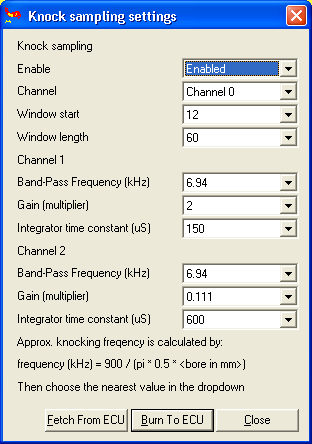
Set Window Start to 12
Set Window length to 60
The knock window is best described using the following graph.
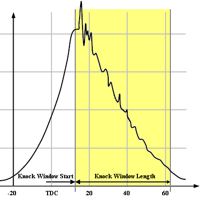
Knock is most likely to occur at the point when the cylinder reaches peak pressure. Assuming that your timing is correctly set up peak pressures will occur between 10-17deg ATDC. The knock window length can be specified between 0 and 60degrees, initially the window should be set to its longest setting but may need to be reduced to increase the accuracy of the detection.
The exact figures will vary depending on your engine's individual characteristics so you will need to tune the Knock Sensor's configuration to insure that you get the optimum function.
Set the Band-Pass Frequency (kHz) to the closest available frequency to the calculated knock frequency.
To calculate your engine's theoretical knock frequency we use the simpe equation: 900/(pi*r)
So using a 81mm bore we can calculate the following knock frequency: 900 / (3.141 * 40.5)
900 / 127.2105 = 7.074kHz
Select the maximum gain of 2. The Bosch sensor will never exceed 2volts (and it would take an explosion to do it), so there is no danger of overloading the sensor.
[dnb] You would never overload the sensor - the sensor produces a voltage proportional to vibration. The danger here is that the knock harware in VEMS either gets too small a signal so you don't see anything if the gain is too small, or if the gain is too big, then there is far too much signal and the output is always clamped at the rail voltage, so you can't distinguish knock from background noise. I do agree that 2 is a good number for the gain.
Select an intergrator time constant of 150uS The intergrator time constant denotes the speed that the VEMS fills its sample value, to fast (a low time value) and you will not get too short a sample, too long and you will not get enough sample data, we'll start tuning this when we set the noise level in the next section.
[dnb] Sampling is the wrong word for this really. The knock chip does sample data from the sensor but it then integrates (effectively performs a running average) it over the selected window. (Remember this window translates from crank degrees into a time period) The integrator time constant denotes the number of "bins" over which we want to calculate this average. If integrator time constant is too long then we get a small output because the average ramps up slowly, and if it is too short then we get a big output (and therefore possibly hitting the maximum value) because the average ramps up quickly.
Setting the noise level
VEMS has Knock values on page 5, so using your termial program type Manmlp05 to switch to the output screen, and mll to see the values:\n�3�
The Values that you are interested in are:
D: xxxx is the signal in the Knock Window Phase, which shows us the noise level where knock is likely to occur.
R: xxxx is the signal value in the noise phase, the noise phase is where knock cannot happen.
The maximum value of D or R is 3FF, we suggest that you tune for a 1/3 of this value to be noise, to set this you will need to drive the car without it knocking and set the noise value to a value averaging 131 to 133. You shouldn't see too much of a difference between D & R at this stage, measurements have shown that the values are around 1.1 to 1.2 times the D value: 14F to 170.
Starting value is Manmttg99c0F To increase the intergrator time constant reduce the number OE to 00, and vice versa to decrease 10 to 1F.
Type mll to see the D & R values after each constant change. Tune the sensor until your R value reads 305 to 307 with normal driving.
Finally type mcs to save, and byebye to take VEMS out of its 'terminal' mode.
If you start to tune your knock window length you may need to reduce your Intergrator Time Constant to increase the signal level.
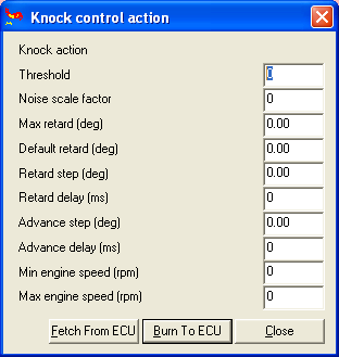
Knock Control Action
Now we've setup looked at the way VEMS identifies knock we can configure its actions when knock is detected.
In the Settings->Knock action window:
Testing Knock Sensor
You will need to use 'Det cans' or another method of listening to the engine so that you can hear the detonation events.
The first and simplest test is to ensure that the knock sensor and your det cans are all working.
In MegaTune go to Tuning->Spark Map and check that the Knock radio button is selected.
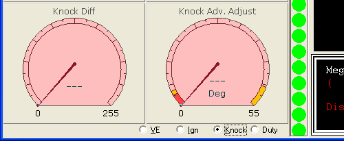
All activity from the knock sensor will be shown on the Knock Diff gauge.
Strike the engine block with a large spanner or wrench away from the and listen for a ringing sound, tests have shown that the bores will ring with the same frequency with this test as they will with detonation. If you hear the ringing sound check the Knock diff reading on the MegaTune window, if there is no reading check your electrical connections, and start to increase the Gain multiplier in the Extras->Knock Sampling Settings menu.
Step 3 - Connecting Output Components
NOTE: VEMS acts as a switch between the Component (injector, relay, ignition coil) and ground. VEMS does not provide the power to these components.
Connecting Ignition Components
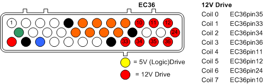
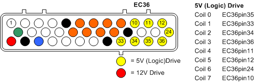
The unit can be ordereed with one of five possible Ignition Channel Options.
Option 8 All 8 channels are high current control channels: (most common)
Option 0 All 8 ignition channels are using logic level(+5v) control for coils that have built in igniters or systems where you wish to use an existing Igniter pack:
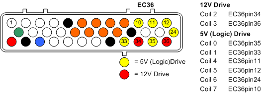
Option 2+6 Two channels are high current, the other 6 are logic level:
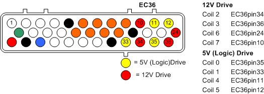
Option 4+4 Four high current channels, Four logic level:
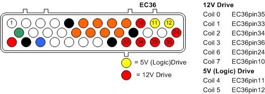
Option 6+2 Six high current channels, two logic level:
Alternative Connection If you are using an external ignition module/igniter pack you can also use the Stepper Motor outputs as control channels:
This method is suitable for 4 cylinder COP/CNP or 4, 6 and 8 cylinder wasted spark.
Example coil connections
The following connections suggest the pin numbers as a suggestion only. The actual connections will depend on the Ignition Channel Options as above.
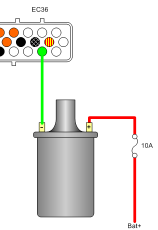
Single coil
In some instances you will want to keep the distributor, in this case VEMS can be configured to use the original coil as shown.
Coil pack
Connecting a two coil (4 cylinder wasted spark)

Additional coil packs, for applications such as 8 cylinder wasted spark

Coil on plug (COP)
Individual Coil connections are shown, the pins connect to the negative '-' side of the coil.

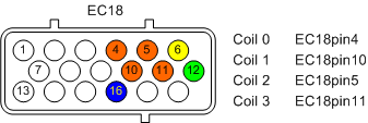
Using the Stepper Motor Driver to control Ignition
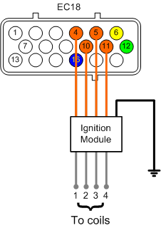
In some cases it has been found that we need to drive external ignition amplifiers (ignitors) using the higher current stepper motor driver.
If you have been using the EC36 plug, the wires must be swapped from the Ingition pins on the EC36 plug and moved to the EC18 plug as follow
- Coil 00 EC36-pin35 to Stepper A EC18-pin4
- Coil 01 EC36-pin33 to Stepper B EC18-pin10
- Coil 02 EC36-pin34 to Stepper C EC18-pin5
- Coil 03 EC36-pin36 to Stepper D EC18-pin11
Enable the Stepper Motor Driver
First we need to enable the Stepper motor output by setting the S259 ch7 output to be permanently on using the waterpump activation.
Go to [tt]Extras->Fan / Water Pump / FuelPump[/tt] and set the water pump Start Temperature to -40 (its default) and its channel to S259 7
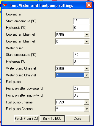
This activates the Stepper chip
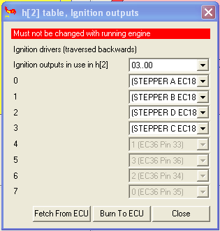
Configure Ingition Outputs
Now we change the ignition outputs [tt]Settings->Ignition Outputs[/tt] from the EC36 pins to their corresponding EC18 pins.
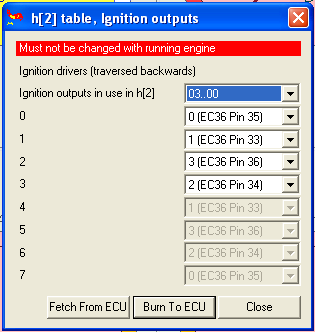
So that the coil drivers are mapped to the pins correctly, reflecting the wiring changes made above.
Wasted Spark
If you're interested in making life easier for yourself, or for running 6 and 8 cylinder engines using the Stepper Driver then wasted spark is answer.
First work out your cylinder pairing:
Four Cylinder
In a 1-3-4-2 engine, cylinders 1&4 and 3&2 can be fired at the same time.
So you connect the wires for cylinders:
- 1&4 to Stepper A EC18-pin4
- 3&2 to Stepper B EC18-pin10
Six Cylinder
In a 1-5-3-6-2-4 engine, cylinders 1&6, 5&2 and 3&4 can be fired at the same time.
- 1&6 to Stepper A EC18-pin4
- 5&2 to Stepper B EC18-pin10
- 3&4 to Stepper C EC18-pin5
Eight Cylinder
In a 1-8-7-3-6-5-4-2 engine, cylinders 1&6, 8&5, 7&4 and 3&2 can be fired at the same time.
- 1&6 to Stepper A EC18-pin4
- 8&5 to Stepper B EC18-pin10
- 7&4 to Stepper C EC18-pin5
- 3&2 to Stepper B EC18-pin11
Configure Ingition Outputs
Ensure that the Stepper Motor Driver is enabled as above. Then configure the outputs, using the Four Cylinder example as above the
Go to [tt]Settings->Ignition Outputs[/tt] and set the sequence:
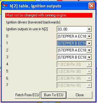
Configuring Ignition
In the 'settings' -> 'Priming, Cranking, Afterstart' window in megatune you find a field called 'Crank Advance(deg)' set that to 0 for now. That will make it easier to set the base timing.
Now make an easy to see mark at #1 TDC on the pulley and strope the engine when cranking. In the 'Settings' -> 'Trigger settings' window in megatune you find a field called 'TDC after the trigger(deg)' Change the value in that field until the timing light show that you have 0 deg timing when cranking.
If you need to set more then around 75 - 80 degrees in that window you should increment the 'Trigger tooth' field in the same window and try again. Each increment will lower the 'TDC after the trigger(deg)' with six degrees.
After you are satisfied with the settings you set the 'Crank Advance(deg)' to 10-15 degrees. You will need to experiment with the advance, this is part of the tuning process. You may find that a level that acceptable for cold start causes problems when the engine is warm.
Wasted Spark COPs
In most OEM applications COPs are fired sequentially, but in cases where no cam sync is present you can setup VEMS to drive the COPs for wasted spark. Selecting Dual Output Mode in 'Settings' -> 'Ignition settings' will group the channels together in pairs: 00&01, 02&03 ... 06&07
The sequence is selected by the even numbered channel.

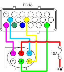
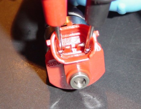
Connecting fuel injectors
VEMS can control anything from 1 to 8 fuel injectors individually, although it's also possible to control upto 16 injectors grouped in twos, although you will need to bare in mind that the grouping of the injectors will change the impedence that VEMS controls. Low Resistance/Impedence (LowZ) injectors need some additional attention which is explained in a later section titled Using LowZ injectors
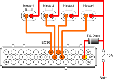
IT IS ESSENTIAL that EC36-pin23 is connected to the Injector's common power supply (see diagram), EC36-pin23 controls the voltage spikes that the injectors produce when they close (flyback), failure to connect the flyback pin will fry your VEMS.
- EC36-pin7 to Injector1
- EC36-pin19 to Injector2
- EC36-pin8 to Injector3
- EC36-pin20 to Injector4
- EC36-pin9 to Injector5
- EC36-pin18 to Injector6
- EC36-pin6 to Injector7
- EC36-pin17 to Injector8
Flyback development
As part of the constant work to perfect VEMS we have found that the use of a 30v Transient Suppression Diode results in an increadably fine grained control of the injectors, all that is required is a diode to be connected in to the flyback line as shown in the next diagram.
Please Note:
- when ordering the controller with 30V flyback, this diode is already inside the controller. An external (2nd) diode MUST NOT be installed, a wire must be used instead
- when using the Transient Suppression Diode you will need to adjust your injector configuration settings. See the section Configuring the Injector's opening characteristics for more details.
This shows the typical installation for a 4 cylinder application.
To 8 injectors are wired as shown here.

And to pair injectors in parallel.

The injector common + signal is connected with a 10A fuse to a switched +12V supply. NOTE the flyback connection is after the fuse.
Configuring VEMS for your Injectors
Injector configuration is handled by the screens Settings->Injector Settings and Settings->Injector Outputs
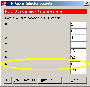
Configuring Injector Sequence
For the purpose if explaination we'll use the example of a four cylinder engine that fires 1-3-4-2. Injectors are controlled using a Binary Mask with the following pattern:
- Injector 1 = 1
- Injector 2 = 2
- Injector 3 = 4
- Injector 4 = 8
- Injector 5 = 16
- Injector 8 = 128
Batch fire
To fire all injectors at the same time the binary pattern will be
1+2+4+8 = 15
So in Settings->Injector Outputs you will set:
- 0 to 15
And in Settings->Injector Settings set:
- Divider to 1
- Alternate banks from h[0] to 0 Only
Fully Sequential
Firstly we need to identify the order of injection, in this case we want to fire in the sequence 4-2-1-3 as 4 will be on its inlet cycle as 1 will be on its combustion stroke.
You will need to set the config.txt entry "alternate" to 03, which will cycle through the first 4 entries STARTING from the furthest right first, which in this case will be the forth number. So you must transpose the firing order to 3-1-2-4.
Remembering the binary pattern above, in Settings->Injector Outputs you will set:
- 0 to 4
- 1 to 1
- 2 to 2
- 3 to 8
And in Settings->Injector Settings set:
- Divider to 1
- Alternate banks from h[0] to 3..0
It is possible to combine groups of injectors using the binary mask and to alternate the group firing using the Alternate banks and Divider settings.
Configuring Injector Flow
Open MegaTune and select the Basic Settings item from the Settings menu. We will need to calculate the value Req Fuel(ms) to suit the injectors we're using.

Basic req_fuel calculation:\n�4�
This is a simplified equation, if you are interested in the reasoning behind it you can read more here: http://www.vems.hu/wiki/index.php?page=GenBoard%2FManual%2FConfig%2FInjectorOpening
Examples\n
850cc injectors on a 2litre engine
6.49 * (1998/4/850) = 3.81mS
So the required fuel value will be entered as 3.8\n
280cc Injectors on a 1.6litre engine
6.49 * (1597/4/280) = 9.25mS
So the required fuel value will be entered as 9.3
It is common practice to then half this number and to double the values in the VE table, as this means that the VE table's resolution effectively doubles and allows finer grain tuning.
Using LowZ Injectors
Fuel injectors broadly fall into two types
- those with a low resistance when measured with a DVM 2-6 Ohm called Low Impedence (many LPG injectors are low impedance)
- and those with resistance readings above 7 Ohm High Impedence.
- the 5.6 .. 5.9 Ohm 1600 cc/min Bosch 0 280 150 846 / 0 280 150 842 (unavailable in 2015) are theoretically low-Z, but most installers used them as high-Z (100% duty, 25.5msec configured, without series resistors): at low duty the heat is insignificant, and at high duty the fuel flow providing sufficient cooling, no overheat failures reported
To drive LowZ injectors using VEMS's advanced (and energy efficient) Pulse Width Modulation (PWM):
Flyback option: [LowZ active flyback 4ch (or 8ch)] recommended (required before PWM-ing is enabled).
- optionally as an upgrade (if it was forgotten at order-time or concept changed later):
- [active flyback addon], v3.8 has separate pads for convenient mounting.
Series "inline" resistors might also work: 4.7 Ohm (preferred) or 6.8 Ohm (50W in any case). Advantage: can be applied with ECU ordered without LowZ active flyback.

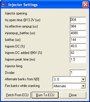
Configuring the Injector's opening characteristics
As you will have seen in the graphs shown above, an injector does not open and close instantly, in fact there are four destinct phases to the process: Injector opening time, Injector ramp up, The injector's full flow, Injector ramp down.
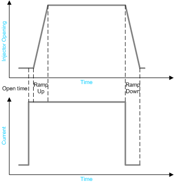
While VEMS takes care of the amount of Injector open time based on its fueling calculations, it needs to factor in the open, ramp up and ramp down times, or too little fuel is added. These times are also voltage dependent as a higher voltage will energise a coil quicker, so we must factor in battery voltage to ensure that the AFR does not lean out with low voltages.
- Inj open time @13.2V (us)
- Inj effective rampup (us)
- Inj rampup_battfac (us)
- battfac (us)
When using a Transient supression diode
- Inj open time should be 0,
- Inj rampup_battfac must be 4080 (which diables the feature)
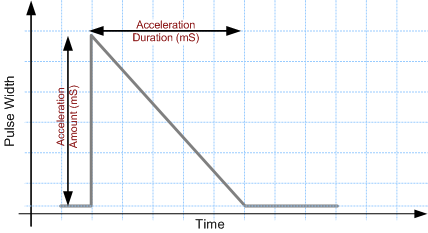
Acceleration Enrichment
The Tip-in values are calculated by a small table defined in the MegaTune window Settings->Acceleration Enrichment:
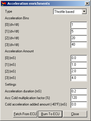
The Acceleration Bins (dv/dt) define the speed of accelerator pedal movement. And the Acceleration Amount defines the corresponding amount of fuel for the acceleration.
The suggested Acceleration Bins the values are shown and will work for most installations. The Acceleration Amounts and Acceleration Duration are the values that will need to be tuned for each installation.
Connecting the fuel pump
The fuel pump is controlled via a mechanical relay.
- EC36-pin15 to relay coil

Idle Air Controller (IAC)
An Idle Air Controller (IAC) is used on most fuel injected engines to provide a method of controling the engine's idle speed. When the car is warming up or an additional load is put on the idling engine such as the additional current of an electical fan or air conditioning compressor it is necessary to raise the engine's idle speed to stop it from stalling.
IAC Types
There are a number of different idle speed controllers:
Wax is the simplest and most common on Japanese cars and are not controllable by the ECU in that they use a wax filled piston which opens the throttle slightly when cold and closes it when the heat causes the wax to expand.
Solanoid IACs use a single coil to open or close a valve in the inlet (in some cases to actually move the throttle plate). The simplest can be either opened or closed and will cause small increase in idle speed. More sophisticated types can be pulsed to provide a variable increase in RPM.
Multicoil and Stepper motor IACs allow a more complex level of control, in its simplest form it will have two coils to open and close the idle valve.
Choosing the correct IAC connection
Single coil types are relatively simple to connect, the only thing you need to know is the resistance of the IAC's coil by measuring it with a DVM. Once you have the resistance value use Ohms law to calculate it's current load. I=V/R.
Examples:
The IAC coil for a Nissan 200SX is measured at ~11 ohms a voltage of 13.8V would mean a current of ~1.26A (13.8/11) which means that a spare high current port (EC36-pins6, 9, 17 or 18) would need to be used.
The Toyota "Idle Up Valve" found on the early 4A engines has a solanoid coil with a resistance of ~44ohms, which gives a current of 313mA(13.8/44). As this is less than the maximum 350mA value for EC36-pin3 (Fast Idle) it would be possible to connect it, but this is only advisable if you are using all the other high current pins. In all other cases its advisable to use one of the spare pins.
Dual Coil Solenoid IAC Control
Found in some BMWs (Bosch) along with Toyota & Subaru, These have three pins, one of which is common, one is a solenoid that opens the idle valve, the other is a solenoid that closes the valve. If neither coil is activated the valve remains in a 50% open poisition (preset-spring type), or moves freely between opened/close position (no spring type).
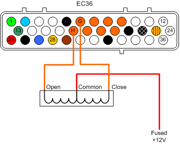
- EC36-pin6 to IAC close pin
- EC36-pin17 to IAC open pin
Configuration
Set IAC actuator speed/pwm freq
stepper speeds : 0 - 976 steps/s, 1 - 488, 2 - 326, 3 - 244, 4 - 195, 5 - 163, 6 - 139, 7 - 122, 8 - 108, 9 - 98, 10 - 89, 11 - 81, 12 - 75, 13 - 70, 14 - 65, 15 - 61.
pwm freq: 0 - 244 Hz, 1 - 195, 2 - 163, 3 - 139, 4 - 122, 5 - 108, 6 - 98, 7 - 89, 8 - 81, 9 - 75, 10 - 70, 11 - 65, 12 - 61, 13 - 57, 14 - 54, 15 - 51.
Stepper Motor IAC
One of the most common types of IACV after the single coil solenoid is the Stepper motor type. The 4 pins of the 2 coils are connect to the 18pin Econoseal plug.
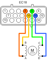
The coils are preferrably connected between A-B and C-D stepper outputs:
- EC18-pin4 Stepper-A
- EC18-pin10 Stepper-B
- EC18-pin5 Stepper-C
- EC18-pin11 Stepper-D
Configuration
Using the dialog Extras->Idle Settings General
Set Control Type to PWM/Stepper
Initially IAC actuator speed/PWM freq should be set to 10, this number will need to be reduced to speed up the stepper, this needs to be done once the idle control is working.
Set Max steps to extend to a low number, as this defines the number of steps that the controller will allow the stepper to make, too many steps will cause the controller to open too far and potentially jump the IACV. Initially start at 50 steps and increase the number once you have stable idle.
Under Iac Hardware setup
Set Type to Stepper
The stepper pattern is defined as a binary pattern where:
Coil A=00 Coil B=01 Coil C=10 Coil D=11
So to define your pattern use the Windows Calculator in binary mode and convert to decimal mode, then put the result in the Iac step sequence box.
For example the typical patterns are
D->B->C->A which is 11->01->10->00 11011000 or 216 in decimal.
D->A->C->B which is 11->00->10->01 11001001 converted to decimal is
201
Connecting A Boost Control Solenoid
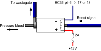
This assumes the use of the Webshop 3-port pneumatic solenoid
Connecting the pneumatic ports
Integral wastegate actuators
Connection option one
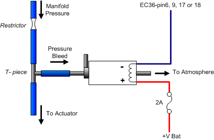
Connection option two
External wastegates actuators
For external wastegates that have two ports (Tial type) that have opening pressure applied to the base of the actuator and a counteracting pressure applied to the top.
"picture to follow"

Boost solenoid electrical connections
- Pin1 to VEMS EC36-pin6, 9, 17 or 18 (exact connection will depend on your configuration and number of connections used for your injectors).
- Pin2 to Fused power supply.
Configuring Boost Control
Before you start to do anything with Boost control Make sure that you have set the Fuel Cut Pressure
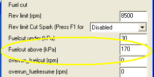
If you have not yet mapped your engine set the Fuel cut value at a little over atmospheric pressure (~102kPa). Because AFRs can spiral out of control very quickly under boost it might be wise to set the fuel cut at 120kPa.
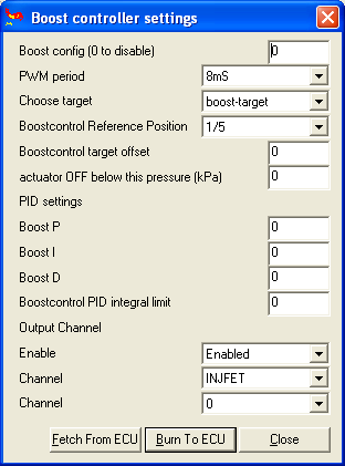
Select the Boost Control Channel
For boost control you will only ever want to select the INJFET channel option as this has the best protection against voltage spikes created by solenoids.
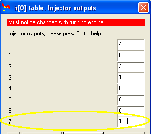
Because you are using the INJFET option you will need to setup the correct channel in Settings->Injector Outputs. Find an unused entry and select an injector FET, the one you select is dependent on which EC36pin you connected to in the same way as we setup the fuel injectors, so for:
- EC36-pin6 (INJFET 6) enter 64
- EC36-pin9 (INJFET 4) enter 16
- EC36-pin17 (INJFET 7) enter 128
- EC36-pin18 (INJFET 5) enter 32
Now we select the boost controller channels in Extras->Boost Controller Settings
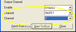
- Enable the controller by selecting Enabled.
- Select INJFET in the first channel drop down.
- Select 7 in the second channel drop down.
Controller Configuration
Set PWM and Boost config
Initial test
Set actuator OFF below this pressure (kPa) to 0, the solanoid should start clicking.
Now check if more air flows if you increase the reference position value. (there are 4 types) 1/5 to 5/5 2 bits in boost_conf, should be selectable in newer megatune profiles
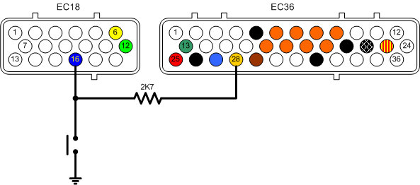
Using Spare Analog Inputs
Depending on the configuration of you VEMS unit there are upto 3 additional analog inputs:
- EC18pin16 Channel 5
- EC18pin6 Channel 6
- EC18pin12 Channel 7
The corresponding channel numbers are use in megatune to define the channel's function:
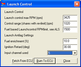
Here we've configured VEMS to activate launch control based on the state of EC18pin16.
Configuring Air Metering
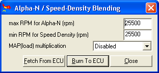
VEMS has a number of strategies to calculate the amount of air entering the engine, Speed Density, Alpha-N, Alpha-N with MAP multiplication, and Alpha-N/Speed Density blending.
The selection of the strategy is made by configuring the Map Mulitplication and Blending values.
Extras->Alpha-N/Speed-Density Blending
Speed Density (MAP vs RPM)
For turbocharged and Normally Aspirated (NA) plenum based engines with mild camshaft timing, Speed Density provides the best metering solution.
Configuration
Set MAP Multiplication to: Enabled
Set max RPM for Alpha-N (rpm) to: 0
Set max RPM for Speed Density (rpm) to: 0
Alpha-N (TPS vs RPM)
Best suited to NA engines running independent throttle bodies (ITBs) where MAP readings are noisy and lack resolution.
Configuration
Set MAP Multiplication to: Disabled
Set max RPM for Alpha-N (rpm) to: 25500
Set max RPM for Speed Density (rpm) to: 25500
Alpha-N with Map multiplication
Turbocharged engines running ITBs are a special case, they have the same problems with MAP noise and resolution when off-boost, but need the MAP to be factored in at anything over atmospheric pressure.
Configuration
Set MAP Multiplication to: Enabled
Set max RPM for Alpha-N (rpm) to: At least 500 to 1000RPM below the max RPM for Speed Density (rpm)
Set max RPM for Speed Density (rpm) to: The RPM below where the Turbo starts to provide positive pressure.
Alpha-N/Speed Density blending
For NA engines with plenums that use more extreme camshafts and as a result have very noisy MAP signal at lower RPMS due to the valve overlap. Configuration values are dependent on the characteristics of the engine.
Configuration
Set MAP Multiplication to: Enabled
Set max RPM for Alpha-N (rpm) to the RPM point just above where the MAP signal starts to read cleanly.
Set max RPM for Speed Density (rpm) to a value just below the Alpha-N value.
Mass Air Flow (MAF)
In cases where a Mass Airflow Sensor is used to provide a Load value.
Configuration
Set MAP Multiplication to: Disabled
Set max RPM for Alpha-N (rpm) to: 0
Set max RPM for Speed Density (rpm) to: 0
Low Current Drivers
A number of pins are available for driving small (350mA) loads such as relays and shift lights
| Econoseal Pin | P259 Channel | Terminal command (on/off) |
| EC36pin3 | P259 chan 4 | mdhb7/mdh37 |
| EC36pin4 | P259 chan 0 | mdh87/mdh07 |
| EC36pin15 | P259 chan 5 | mdhd7/mdh57 |
| EC36pin16 | P259 chan 1 | mdh97/mdh17 |
| EC36pin30 | P259 chan 7 | mdhf7/mdh77 |
| EC36pin31 | P259 chan 6 | mdhe7/mdh67 |
For those of you who are interested mdh stands for menu debug hardware
Using Low Current Drivers for a Shift Light
Connect a 12v indicator lamp to a switched supply and taking your choice from the table above, connect the lamp's second pin to the VEMS.
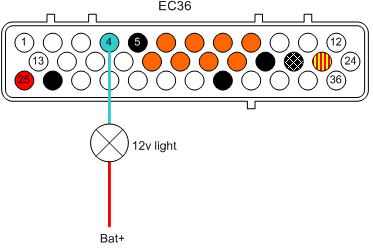
Configuration
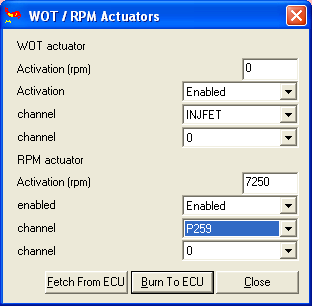
In this example we have connected the light to EC36pin4 which is P259 chan0. To set this light up as a shift light pull up Extras->WOT / RPM Actuators and setup the RPM actuator.
- Activation (rpm) - is set to the value you want the light to come on at.
- Select Enabled to activate the function
- Channel P259 Channel 0 - as we're connecting the light to EC36pin4
Connecting the LCD (Optional)
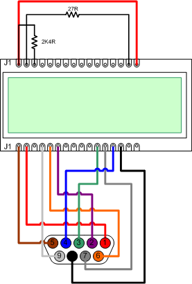
The LCD option can be a addition to your VEMS module - with the use of an IBM PC keyboard it becomes possible able to configure your system without having to constantly use a laptop. In the first instance it will provide a method of checking that your VEMS system is working. At present the LCD is provided without wiring, so you will need to connect it using a Female DB9 plug in the following way:
To control brightness and contrast (connection advice)
- LCD-J1 to LCD-J16
- LCD-J1 to LCD-J3 (2,4K ohm resistor)
- LCD-J2 to LCD-J15 (27 ohm resistor)
- LCD-J1 to DSUB9-pin5 (brown)
- LCD-J2 to DSUB9-pin1 (red)
- LCD-J4 to DSUB9-pin9 (white)
- LCD-J5 to DSUB9-pin6 (orange)
- LCD-J6 to DSUB9-pin2 (violet)
- LCD-J11 to DSUB9-pin3 (green)
- LCD-J12 to DSUB9-pin7 (grey)
- LCD-J13 to DSUB9-pin4 (blue)
- LCD-J14 to DSUB9-pin8 (black)
Pin outs
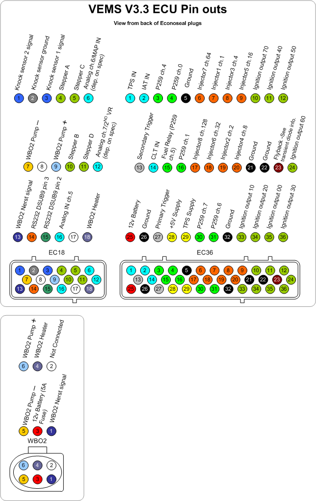
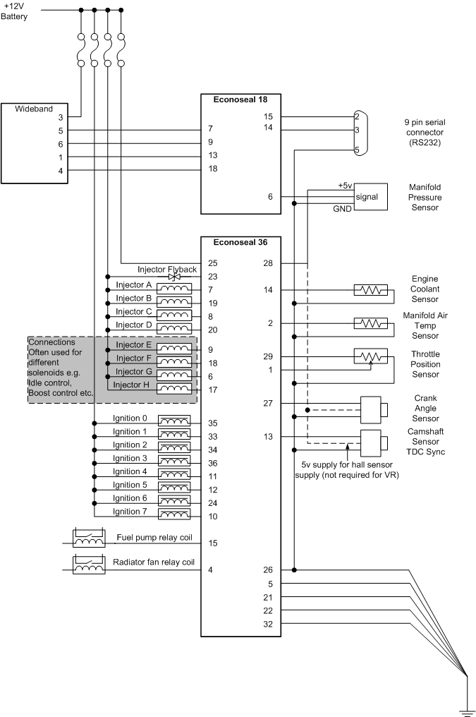
Schematic Wiring Diagram