Round hardware
Subpage of Round
Round Hardware
- Connectors Pinouts:
- RS232 - DSUB9 female. Note that any extension cable needs to be straight through and not cross-over.
- 2: RX
- 3: TX
- 5: GND
- Main connector - DSUB15 male.
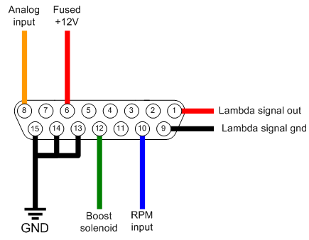
- On Round V1 (serial number is under 3000):
- Note that the (now standard) flying loom version has the WBO2 pins on the WBO2 connector, so those 5 pins (pin 2,3,4,5 and 7) of the DSUB15 are NOT connected:
- 1: Vout (Lambda output signal +) - configurable as either Narrow band, wideband 0-1v through to 0-5v.
- 6: VBatt+ (12V)
- 8: analog input for conditioned signal or NTC-type temperature sensor. The input has internal pullup to 4V. As a side-effect, an unconditioned signal (TPS) can slightly be raised (recalibrate TPS, or use 10k series resistor to decrease this effect). Pressure-sensors (MAP and boost) and MAF are usually conditioned (though we heard that a certain MAF was not), see: Analog input settings
- 9: Vout-gndref (voltage output signal) -. Connect to GND or max 2..5V potential (with higher voltage on this pin, max output voltage on Vout will be limited).
- 10: RPM/Wheel Speed input
- 11: RPM reference (input threshold can be adjusted; normally leave open)
- 12: 5A Power control (Boost output)
- 13: Power GND connect all GND-s
- 14: Power GND connect all GND-s
- 15: GND (Power or signal) connect all GND-s. If you connect this ground to the EGT- (sensor - white wire) than this can be separate from the pin14 and pin14 (pin12 and pin14 always used for powerGND)
- Also wire supply voltage to WBO2 Heater to sensor pin 3 through 5A fuse (already wired this way in the supplied harness)
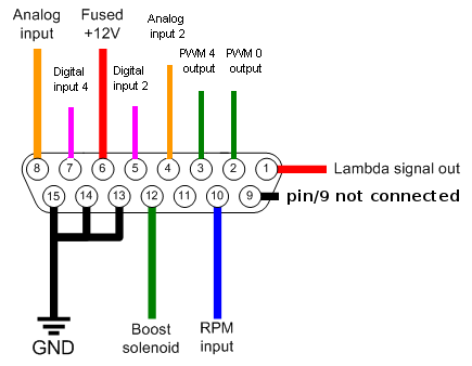
- On Round V2 (serial number is from 3000):
- Note that the (now standard) flying loom version has the WBO2 pins on the WBO2 connector, so those 5 pins (pin 2,3,4,5 and 7) of the DSUB15 are NOT connected:
- 1: Vout (Lambda output signal +) - configurable as either Narrow band, wideband 0-1v through to 0-5v.
- 2: 5A Power control (PWM 0 output) Protected with flyback diode, connect max VBatt+ (absolute maximum is 15V)
- 3: 5A Power control (PWM 4 output) Protected with flyback diode, connect max VBatt+ (absolute maximum is 15V)
- 4: analog 2 input (0-5V maximum)
- 5: digital input 0 (0-5V maximum)
- 6: VBatt+ (12V)
- 7: digital input 4 (0-5V maximum)
- 8: analog input for conditioned signal or NTC-type temperature sensor. The input has internal pullup to 4V. As a side-effect, an unconditioned signal (TPS) can slightly be raised (recalibrate TPS, or use 10k series resistor to decrease this effect). Pressure-sensors (MAP and boost) and MAF are usually conditioned (though we heard that a certain MAF was not), see: Analog input settings
- 9: Vout-gndref (voltage output signal) -. Connect to GND or max 2..5V potential (with higher voltage on this pin, max output voltage on Vout will be limited).
- 10: RPM/Wheel Speed input
- 11: RPM reference (input threshold can be adjusted; leave open)
- 12: 5A Power control (Boost output) Protected with flyback diode, connect max VBatt+ (absolute maximum is 15V)
- 13: Power GND connect all GND-s
- 14: Power GND connect all GND-s
- 15: GND (Power or signal) connect all GND-s. If you connect this ground to the EGT- (sensor - white wire) than this can be separate from the pin14 and pin14 (pin12 and pin14 always used for powerGND)
- Also wire supply voltage to WBO2 Heater to sensor pin 3 through 5A fuse (already wired this way in the supplied harness)