Round analog input settings
Subpage of Analog Menu
Analog input settings
0-5V analog signal can be connected to the analog input (DSub15/pin8). Useable for display (scale adjustable), or for Boost control.
On rounds with serialnumber < 2900 the Analog input is shared with the internal Button so when connecting something (like a 400 kPa MAP sensor) to analog input, the "button threshold" might require adjustment.
Analog input
- Rounds with serial number > 2900 Button threshold: (0=disable, 255=always push, 3 is the default value)
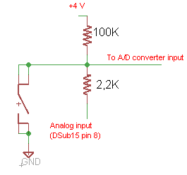
- RoundV2 has multiple analog inputs, this only applies to the first analog input: 100K pullup to 4V and a 2.2K series resistor on the input.
- The internal button can pull down the input to GND.
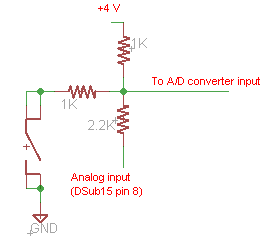
- Rounds with serial number < 2900 Button threshold: (0=disable, 255=always push, 165 is the default value, or see below if analog input is in use)
- It has a 1K pullup to 4V and a 2.2K series resistor on the input.
- The internal button has a 1K resistor to pull down the input.
Setting "button threshold" on round with serial number < 2900 . Especially important when analog input is in use (say, a 400 kPa absolute pressure "MAP" sensor):
- See "ADC raw" gauge while pressing/releasing button ("ADC raw" is high resolution 0-65535: it shows 256 times higher values than the button threshold).
- Take note of the button pressed / released values, choose a value in between these (eg. the average), and divide by 256. Configure the button threshold to this value.
- Note: at idle, say 45 kPa absolute pressure with MAP signal connected to analog input, BOTH pressed/released ADC raw values will be lower than at 101 kPa engine off.
- If the chosen value is lower than the released@45kPa but higher than pressed@101kPa, than you'll be able to change display state with the button both at idle and engine off (perhaps not at high boost). Should you have any issues, include these ADC_raw values in the support query (but dividing by 256 is easy if there is a difference between pressed and released values).
- Make sure the WBO2 pins are not accidentally touching or grounded (WBO2/pin5 pump- pin has 4V on it, if accidentally grounded - make sure it's not -, would effect the internal operation)
The displayed value calculations:
Displayed value = Analog input curve (A/D in) * Analog input calibration / 32 + Analog input offset.
Dot placement: it sets the dot position on display if shows the analog value.This is a fix position and does not depend on Analog value.