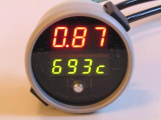
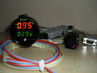
VEMS EAW-52 Round dual-display gauge ( 52mm WBo2 + EGT meter with lotsof extras )
Pinouts [here] eg. [WBO2 wire-colors] with new wire-colors on page1, old colors on page2 (trivial to tell which one applies).
Roundv1
[Purchase Roundv1_WBO2_EGT here]
Roundv2
- more analog inputs - useful for logging, or the control loops
- 3 power outputs with firmware support for (currently) 3 independent control loops (+WBO2 has additional power output and 2 control loops)
- more flashspace available for future firmware features
- 6 extra multicolor (red-green-yellow) status LEDs
[Purchase Roundv2_WBO2_EGT here]
- AfreshTiny/FirmwareUpgrade
- The recommended software for firmware upgrade and adjustments is VemsTune (Tools menu), where it's just one keypress to set reasonable DISPLAY-MODE after a firmware upgrade.
- Really read the upgrade instructions on AfreshTiny/FirmwareUpgrade if not using VemsTune. If not using the recommended software, and not reading the instructions, then when upgrading round to 2010-09-xx (or newer) firmware the old way (".bat" but why would anyone use that ?), upload config or adjust the display mode manually''' (otherwise display might be blank, which is a valid mode, it was requested for "night-cruising").
- AfreshTiny/DisableAim
- AfreshTiny/VoltageOutput
- AfreshTiny/WidebandCalibration
- AfreshTiny/AnalogInput
- AfreshTiny/EgtCalibration
- AfreshTiny/RpmInput
- AfreshTiny/DemoRound (display constant text, eg. shop window)
- AfreshTiny/AimDisplay (v3.x => RS232 => round displays runtime data )
- AfreshTiny/OtherUses other functions, mainly brainstorming
Firmware Releases
[VemsTune] is required for round firmware upgrade and operation for both the Aim and Non-Aim firmware.
Stable releases:
- Non-AIM: 1.5.8
- AIM: 0.5.8
For testing only:
- Combined AIM / Non-AIM for Roundv2:
- 1.5.9, this firmware supports full control functions while also allowing display of AIM stream data.
- 1.5.10, (idle) rpm targets higher range was max 4080, now max 16320 requires [VT Dev 2015-04-04] or newer; More versatile to allow use of Boostcontrol/PWM0/PWM4 outputs to control shiftlights (blinking/non-blinking).
- Normal Non-AIM for Roundv1:
- 1.5.9, no changes for Roundv1
- 1.5.10, (idle) rpm targets higher range was max 4080, now max 16320 requires [VT Dev 2015-04-04] or newer; More versatile to allow use of Boostcontro output to control shiftlight (blinking/non-blinking).
Firmware features
Since this is meant as an easy-to-use device, first only very few features are supported.
- WBO2. Lambda value matches Bosch (manufacturer of the LSU4 sensor) specifications. Tested against very expensive 6-gas analyzers (with 2 - different - sensors in same exhaust stream) with very good match (showing 0.86 / 0.87 when the high-end analyzer displayed 0.86 lambda)
- EGT with cold-junction measurement and null-offset calibration
- onboard-temperature measurement
- data can be logged to PC for further analysis
- self-calibrating (no setup required, just plug and play)
- RPM input (VR or HALL, several trigger-types)
- for logging
- or (RPM-dependent) boost-target
- or vehicle-speed
- analog inputs with configurable sensor curves and scaling
- boost control
- configurable analog voltage output
New features supported since 2010-03-29 firmware
- boostcontrol
- multiple RPM bins for boosttarget
- multiple RPM bins for boost reference PWM (refdc)
- These adjustable RPM bins provide fine control. (Note: in v3.x, (RPM,gear) can be used for even finer control)
- idlecontrol
- and producergas/woodgas mixture lambdacontrol (for engines that run on wood/waste)
- the air-mixing valve can be a 2-wire VW / Audi (VAG) PWM idle-PWM solenoid. Avoid the bigger "limphome" model that is open at 0%, closes most at 25%, and opens again from 25..100%
Display features
- Holding the button steps to next slot appr. every seconds (no need to press button many times)
- if enabled. shows "S-0" .. "S-7" (the next slot index) while pushing the button
- this can be disabled in display settings menu
- Show peak value (>= fw 1.5.7).
- Independently configurable for all 8 display slots Top and Bottom entries
- shown peak value reset when display slot changed with button or from VemsTune
- see [related VemsTune dialog].
- Useful for peak MAP, peak RPM, max temperature, max speed, whatever...
- Blank display, for "night-cruising"
- NO-Aim version:
- select blank.x for any slot (in display mode menu) - Round displays blank with only one dot (fixed dot position)
- OR select blank c0 .. c4 (in display mode menu) for any slot. Set the dot position in aim custom settings (adjustable dot position)
- Aim version:
- select for example "custom aim 3" (or other 0..4) (in display mode menu) for any slot
- AND (in aim custom settings menu), "custom 3 mul" = 0. Zero multiplier has special meaning: blank.
- set "custom 3 dot position"
- NO-Aim version:
Related Software
- VemsTune
- Latest test releases : http://vems.hu/vt/
- Required for gauge configuration, datalogging and firmware upgrades
- [VemsTune help]
- MegaTune (VemsTune is recommended instead)
- Latest releases : http://www.vems.hu/download/round/
- log data to disk the same way as with v3.x (File -> Datalog) or click the "Log" icon (turns green when logging)
- log analysis: vemslog viewer (or any LogAnalysis program that can take xls input)
Documentation
Warning: the WBO2 sensor in the exhaust is ruined quickly if not heated. When the engine is running, keep the controller running too (so it keeps the sensor heated) or remove the sensor from the exhaust (and use a M18x1.5 mm plug).
- Round warning paper with WBO2 wire colors: http://vems.hu/download/round/docs/Round_pins1.pdf
- We supply this printed paper with each round. This allows customers to push in the 6 WBO2 receptacles in the connector housing correctly (several customers asked that the WBO2 pins are not inserted in the connector housing during manufacturing, so they can pull through the firewall).
Mounting
Allows mounting even with the tightest available space:
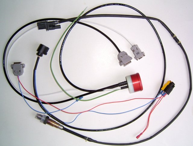
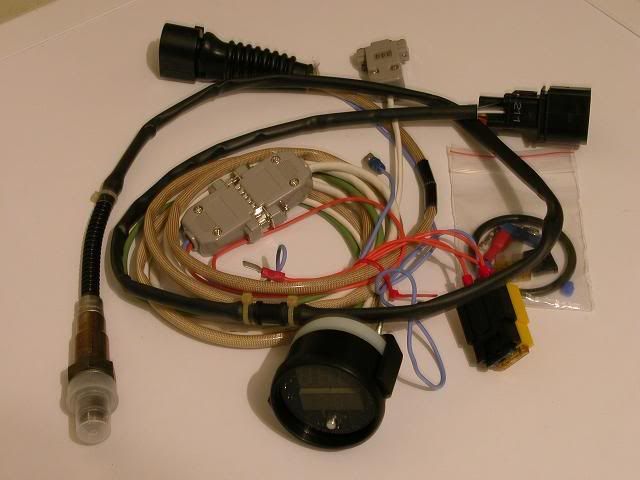
U-bracket mounting bracket:
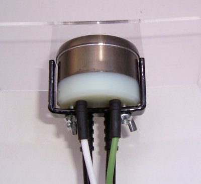
The simple factory "harness" (with the DSUB15 female) only has supply wires and a fuse:
- +12V must be connected to the fuses (the wideband sensor internal heater consumes max 3A). Red wire on the picture.
- GND must be connected to the DSUB15 connector (blue wire on the picture)
- if you need special functions, like analog output, you need to open the DSUB15 and solder wire to the chosen pin (see pinout below)
- the EGT has a green cable with green (+) and white(-) wires: 25C/mV (=40uV/C in other words) sensitivity (offset and gain calibration capability in software): 0..48mV DC input for 0..1200C (+cold junction temperature must be added, that is inside the round case, normally appr 30C) and WBO2 use separate cables):
To connect for the WBO2 and EGT functionality is trivial (including datalogging with PC). The RPM input and voltage output has some options, detailed below (these functions are rarely used, but sometimes very useful).
The manufactured version features:
- 3 digit 7 segment LED (with dots)
- 4 digit 7 segment LED (with dots)
- Voltage output. High resolution (up to 5V, 12bit, programmable output curve)
- RS232 level
- directly plugs into PC
- or USB-RS232 adapter
- or small dongle for CAN-physical layer bus (will not need to be removed from network even for firmware reflash!)
- free outputs
- power
- signal level (0..5V high resolution, external ground referenced)
- extra inputs
- analog input
- RPM input, or vehicle-speed (kmh / mph) or other frequency signal
- button
Free air calibration
The RCal resistor in the sensor is supported, so calibration is not necessary. The optimal PID parameters are different in the exhaust stream and free air, so don't worry if free air reading is slightly off or even floating somewhat. Note that toleration in the lambda range is very good: 5% error means (actual => reading) 0.8 => 0.81 lambda (since the difference from lambda=1.0 counts, which is 0.2 and 0.19 respectively).
Connector Pinouts
RS232 - DSUB9 female. Note that any extension cable needs to be straight through and not cross-over.
- 2: RX
- 3: TX
- 5: GND
Main connector - DSUB15 male.
On Round V1 (serial number < 3000) 5 pins (pin 2,3,4,5 and 7) of the DSUB15 are NOT connected
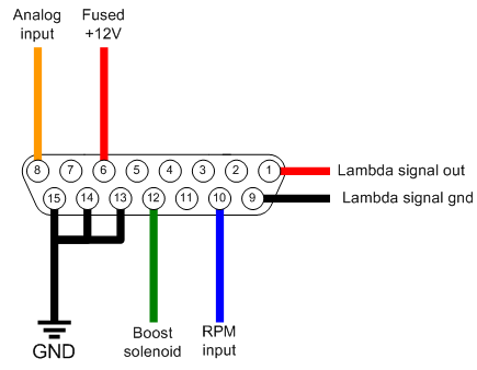
- 1: Vout (Lambda output signal +) - configurable as either Narrow band, wideband 0-1v through to 0-5v.
- 6: VBatt+ (12V)
- 8: analog input for conditioned signal or NTC-type temperature sensor. The input has internal pullup to 4V. As a side-effect, an unconditioned signal (TPS) can slightly be raised (recalibrate TPS, or use 10k series resistor to decrease this effect). Pressure-sensors (MAP and boost) and MAF are usually conditioned (though we heard that a certain MAF was not)
- 9: Vout-gndref (voltage output signal) -. Connect to GND or max 2..5V potential (with higher voltage on this pin, max output voltage on Vout will be limited).
- 10: RPM/Wheel Speed input. This input is internally protected ( +-15V capable ) but also sensitive (can sense 0/3V or even 0/1V or downto +-250mV VR signal if sufficiently biased)
- 11: RPM reference threshold voltage of the RPM input can be adjusted; leave open unless needed:
- pull with a 47k..100k resistor to 0V to make it sensitive to extremely low signal
- or pull with 47k..200k resistor to +12V to make it less sensitive (need higher peak, but tolerate more noise)
- Normally a frequency signal (0/3V or 0/5V or 0/12V type) goes below 0.3V each pulse. For a certain Motronic 0.8V / 11V tachout signal, a 100k pullup resistor to +12V was used on pin11 RPM reference input to raise the threshold voltage (of RPM input pin10), and read tach-signal. (Other option was to 1/4 divide the RPM input voltage eg. with resistors 6k8 and 20k : 1 / (20 / 6.8 +1) = 0.25 appr (or slightly lower if considering input impedance)
- 12: 5A Power control (Boost solenoid) Protected with flyback diode, connect max VBatt+ (absolute maximum is 15V)
- 13: Power GND connect all GND-s
- 14: Power GND connect all GND-s
- 15: GND (Power or signal) connect all GND-s. If you connect this ground to the EGT- (sensor - white wire) than this can be separate from the pin14 and pin14 (pin12 and pin14 always used for powerGND)
- Also wire supply voltage to WBO2 Heater to sensor pin 3 through 5A fuse (already wired this way in the supplied harness)
On Round V2 (serial number > 3000)
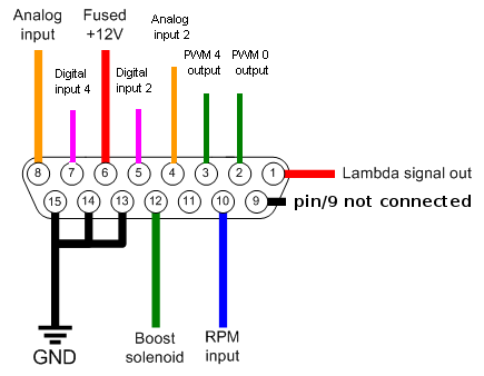
- 1: Vout (Lambda output signal +) - configurable as either Narrow band, wideband 0-1v through to 0-5v.
- 2: 5A Power control (PWM 0 output) Protected with flyback diode, connect max VBatt+ (absolute maximum is 15V)
- 3: 5A Power control (PWM 4 output) Protected with flyback diode, connect max VBatt+ (absolute maximum is 15V)
- 4: analog 2 input (0-5V maximum)
- 5: digital input 0 (0-5V maximum)
- 6: VBatt+ (12V)
- 7: digital input 4 (0-5V maximum)
- 8: analog input for conditioned signal or NTC-type temperature sensor. The input has internal pullup to 4V. As a side-effect, an unconditioned signal (TPS) can slightly be raised (recalibrate TPS, or use 10k series resistor to decrease this effect). Pressure-sensors (MAP and boost) and MAF are usually conditioned (though we heard that a certain MAF was not)
- 9: Vout-gndref (voltage output signal) -. Connect to GND or max 2..5V potential (with higher voltage on this pin, max output voltage on Vout will be limited).
- 10: RPM/Wheel Speed input. This input is internally protected ( +-15V capable ) but also sensitive (can sense 0/3V or even 0/1V or downto +-250mV VR signal if sufficiently biased)
- 11: RPM reference threshold voltage of the RPM input can be adjusted; leave open unless needed:
- pull with a 47k..100k resistor to 0V to make it sensitive to extremely low signal
- or pull with 47k..200k resistor to +12V to make it less sensitive (need higher peak, but tolerate more noise)
- Normally a frequency signal (0/3V or 0/5V or 0/12V type) goes below 0.3V each pulse. For a certain Motronic 0.8V / 11V tachout signal, a 100k pullup resistor to +12V was used on pin11 RPM reference input to raise the threshold voltage (of RPM input pin10), and read tach-signal. (Other option was to 1/4 divide the RPM input voltage eg. with resistors 6k8 and 20k : 1 / (20 / 6.8 +1) = 0.25 appr (or slightly lower if considering input impedance)
- 12: 5A Power control (Boost solenoid) Protected with flyback diode, connect max VBatt+ (absolute maximum is 15V)
- 13: Power GND connect all GND-s
- 14: Power GND connect all GND-s
- 15: GND (Power or signal) connect all GND-s. If you connect this ground to the EGT- (sensor - white wire) than this can be separate from the pin14 and pin14 (pin12 and pin14 always used for powerGND)
More printable user-guides are at:
- http://vems.hu/download/round/docs/
- [VemsTune help]
- the VEMS Round device is also known as Smart-Round-Dual (old name: AfreshTiny).
