Subpage of Base setup menu
Wideband settings
Wideband quickstart checklist
- Wire up your sensor according to instructions in section wideband hardware
- Configure correct sensor type for each channel (LSU4.9 or LSU4.2)
- Apply WBO2 default settings (from the bottom of dialog dropdown) for heater/pump and warmup, do not change the PID settings (from default) unless you know what you are doing.
- Make sure the factory calibrations for pump zero and nernst DC target are matching your ecu papers
- Fill default Ri target for both channels (=165)
- Review additional specific instructions per sensor type
- Calibrate per channel (see below)
Calibration
- Remove the sensor from exhaust, calibrate the sensor in free air
- In the WBO2 calibration dialog:
- Select the sensor you want to calibrate (either first or second).
- Make sure the sensor has power (fuse plugged in)
- Start calibration with some low calibration value, eg. 50 (not 255) or the previous
- Press start cal for manual calibration or auto cal for automatic
- When sensor is warm after ~1 minute, adjust sensor calibration until O2 displayed=20.9% (20..22%); make sure the free air is refreshed by waving the sensor a bit.
- Press burn; it will safe to the selected calibration value (either sensor 1/2), press stop cal to stop.
- Take note of the value in the install log, preferrably also take note of the sensor Rcal resistance (with sensor unplugged, measured between sensor pump+ and rcal pins, usually between 60..300 Ohm).
- Put the sensor back in exhaust, proceed to second sensor if needed
Wideband calibration is a good verification of the setup, necessary to repeat if something is changed in either sensor, connections or configuration.
Note: While the sensor looks rugged externally, its internal ceramic element is quite fragile. Handle with care, do not drop on the floor and do NOT leave in the exhaust when not controlled (but engine is running, the carbon deposit buildup will kill the sensor).
Therefore ALWAYS remove the sensor from the exhaust when not controlled (or if oil or coolant contamination is expected), before starting the engine.
Both Bosch LSU 4.9 and (the older) LSU 4.2 probes are fully supported by Vems dual internal wideband controllers, under similar conditions LSU 4.9 probe has
faster response (than LSU 4.2) and longer expected lifetime.
This section will outline connecting and wiring up the wideband probe to your ecu and emphasize the differences between LSU 4.2/4.9 probe hookup.
*** Take care, LSU 4.2 and LSU 4.9 have different connector pinouts ***
| Wideband sensor connection to controller | ||||||
| Function | Cable color | LSU 4.2 pin | LSU 4.9 pin | V3 WB1 pin | V3 WB2 pin | Notes |
| Pump+ | Red | 6 | 1 | EC18/9 | EC18/8 | |
| Pump- | Yellow | 5 | 2 | EC18/7 | EC18/7 | |
| Nernst | Black | 1 | 6 | EC18/13 | EC18/1 | LSU 4.9 see pullup resistor note below |
| Heater- | White | 4 | 3 | EC18/18 | EC18/17 | |
| Heater+ | Grey | 3 | 4 | +12V fused | +12V fused | |
| Rcal | NC | 2 | 5 | NC | NC | no wire to sensor (see Rcal below) |
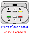
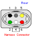
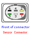
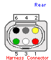
| Check sensor connector orientation by LSU Rcal pin (sensor wire missing) and by wire color, do not just follow drawings without checking | ||||||
| Wideband sensor connector pin numbering | |||
| LSU 4.2 | LSU 4.9 | ||
| 0 258 007 057 | 0 258 017 025 | ||
 |
 |
 |
 |
|---|---|---|---|
Additional specific instructions per sensor type
- LSU 4.2
LSU 4.2 must be selected in config (Wideband settings: independently possible for 1st and 2nd WBO2 channel), default PID values work (eg. Ri target is 165), no specific firmware requirements. Warning: Selecting LSU 4.2 for an LSU 4.9 sensor will apply more heat and result in reduced sensor lifetime (and measurement precision suffers also, of course).
LSU 4.9
If the ECU is for Audi AAN with motronic55 connector, or was ordered with "nernst pullup" requested, than LSU 4.9 can be connected without anything special (other than selecting in config).
Verify with this quick method: Power up ECU and measure nernst voltage (with nothing connected, config does not matter at this point). If less than 4.3V (above GND), then install a 27k resistor between nernst and +5V for correct operation (pullup resistor for nernst reference current according to Bosch requirement: nernst reference current replaces the LSU 4.2 reference oxygen gas connection-tube, which was sensitive to clogging).If the 27k nernstpullup resistor is installed (inside the box or outside), nernst measures >4.3V (typically appr 4.9V) when open circuit. With a 1k pulldown (test resistor towards GND) measures typically appr 175-180 mV => don't install another 27k externally if already installed internally.
Requires ecu firmware >= 1.2.30, LSU 4.9 must be selected in config (Wideband settings: independently possible for 1st and 2nd WBO2 channel).