Subpage of Inputs menu
Table Of Contents
Knock system outline
Knock sampling setup
Knock detection setup
Knock control action setup
Knock system outline
Vems Advanced knock control system can detect engine knock reliably and differentiate its characteristic sound from
normal engine noise using the vehicle's original, factory-fitted knock sensors, to detect detonation.
To improve this detection and reduce the influence of background engine noise a combination of a configurable knock window start angle/length and
frequency filtering is used.
The engine sound energy during engine operation will vary for different frequencies in the spectrum. The knock sound energy will be more prominent
at certain frequencies. A competent tuner needs to carry out a frequency analysis to determine the frequency where the difference of the engine sound
with and without detonation is most clear to detect. The center frequency setting of the Knock system must match this frequency. The Knock Control
system in the ECU can then be configured to adjust the ignition according to measured knock levels.
Knock Sensor
The knock sensor measures the engine vibrations and turns this into an AC waveform output.
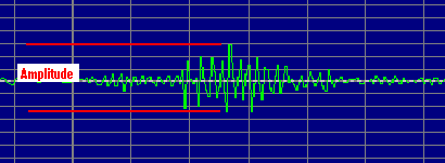
Audio signal output from a knock sensor
With increasing engine RPM, the higher engine vibrations will result in an increase in the amplitude of the knock sensor signal. A race engine operating
at high RPM will show high amplitudes making it difficult to detect knock.
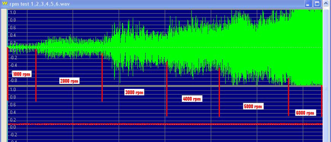
Knock sensor signal with increased engine RPM
Vems Advanced knock control system improves knock detection by reducing the influence of background engine noise using a combination of knock data windowing, frequency filtering and definable background noise tables.
Knock window
The knock window is the period in the combustion cycle during which knock is likely to occur, normally between 10 and 50 degrees
after TDC (top dead center). The ECU sends a knock window signal to onboard knock control chip to mark the start and end angle in the engine
cycle. The knock chip will measure the knock sensor signal during this window and sends the information to the ECU. The ECU uses the
measurement to calculate the knock levels for each cylinder of the engine.
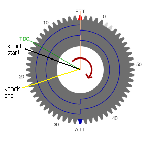
Knock window relation to engine cycle
Frequency Bandpass Filtering
To correctly identify knock, the ecu bandpass filter must be set to match the theoretical best center frequency. The center frequency
is normally set to the frequency of the engine that shows the greatest energy difference between normal engine
operation and active detonation. Although this can be determined by frequency analysis as a good default this can be calculated as follows:
Knock frequency (kHz) = 900/(Pi * d * 0.5) where d = the bore in millimeters.
The knock chip filters and amplifies the signal transmitted from the knock sensor based on
the center frequency. Signals of the selected center frequency pass the frequency filter amplified, while signals in other
frequencies will be reduced. The further away from the center frequency, the more the signal will be reduced. Filtering will reduce the
influence of background engine noise resulting in improved knock detection.
Gain Factor
A gain factor is required for knock sensors which normally have a relatively low signal output level. Vems has a dual channel knock interface, this allows you to choose, per cylinder, the knock sensor which is the closest (in distance) to the cylinder in question and to set the gain on a per cylinder base.
Knock sampling setup
In this section we will be focusing on the settings of the advanced knock control system which are related to the sampling of the knock data. Below you find an example of the
knock settings dialog as it is available in inputs/knock sampling in VemsTune. The variables which are needed for the setup of knock sampling only (the rest we will outline in the next
paragraphs) are highlighted in the red rectangle.
Within vemstune we have included several safe defaults for you to use. It is highly recommended to start out using one of these defaults; the default selection is available in the area within the
yellow rectangle. In this example we are using "Enabled_All_Ch1_Log_Only".
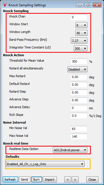
Knock sampling settings VemsTune dialog
Knock Sampling Settings
Knock Channel: This is the decimal representation of the knock channel byte from the input/knock channels drop down list, you should not have to modify this manually
Knock Window Start: The knock window start angle in degrees (ATDC)
Knock Window Length: The knock window length in degrees
Knock Band-Pass Frequency (kHz): The center frequency of the knock band pass filter, this should be set to the calculated knock frequency of your engine (see frequency bandpass filtering section for
more details); Example a BMW m54b25 engine (6 cyl 2.5 liter) with 85mm bore:
Knock frequency (kHz) = 900/(Pi * 85 * 0.5) = 6.741 kHz.
Choose the nearest frequency from the dropdown list, in our example this would be 6.64 kHz.
Knock Integrator Time Constant (uS; takes effect after burn and ECU reboot): Works as an amplifier, we will use this together with channel gain setting to get our reference measurement setting correct. Larger time constant results in lower knock reading.
For the best accuracy try to keep time constant between 100-150uS and use lower gain settings
Knock Realtime Data
Realtime data option: Very useful during tuning (the knock flag is for indication, stays lit for seconds as racing drivers requested). This option allows you to switch realtime data stream the ecu transmits to VemsTune, you can select either "ADC/Individual power" or "Individual knock data" keep in mind that you can only watch
one stream, not both at the same time. It is recommended to use "ADC/Individual power" in most cases this still allows you to watch individual knock channel data (although at slightly lower resolution) without compromising
the individual power data. For setting up knock gain and cylinder calibrations (or if you prefer to monitor high resolution knock data above individual power data) it is possible to select "Individual knock data" when this
option is selected the Individual power gauge and logging of its data is disabled.
Knock Sampling Base Reading Calibration
When setting up your knock control sampling we will start out from the save defaults as outlined in the previous paragraph, this also includes safe settings for the dialogs inputs/knock channels and inputs/knock gain and ref. Examples of what your dialogs should look like if you have successfully applied the default "Enabled_All_Ch1_Log_Only":
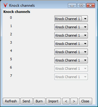
Knock channel settings VemsTune dialog
In this example setup we have loaded a default which uses knock sensor 1 for all cylinders, if your engine is equipped with multiple knock sensors make sure you choose the right sensor for each cylinder. The right sensor for your cylinder is the sensor which is the closest (in absolute distance) this usually gives the best reading for that specific cylinder.
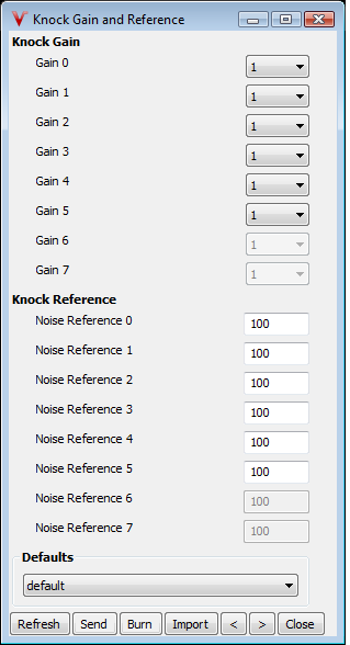
Knock gain and reference settings VemsTune dialog
Before starting the actual calibration process you need to calculate the knock frequency for your engine bore and select this in the band pass frequency dropdown. For proper setup of gain levels also need to make sure that in the dialog inputs/knock sampling settings, section "realtime data option", the option individual knock data is selected (bottom red box from the dialog of previous section). Updated dialog with settings for our example engine (highlighted in purple).
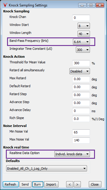
Knock sampling with updated bandpass settings m54b25
It is now safe to start up the engine (prerequisite for this being that there is already a tuned map in your ecu to start engine on). Knock sample base reading can be calibrated in a few simple steps:
- If you open up the knock screen in VemsTune/View/Group/Knock, you should see monitoring of individual knock values for each cylinder. With the same gain level for each cylinder you will most likely notice some cylinders produce a bit higher knock level than others and the knock level mean might be at a sub-optimal level for accurate knock detection.
- Our aim is to get the average knock value for all cylinders around the knock reference average both values are in the bottom side of your knock screen in VemsTune. This should be done at one specific engine rpm and low load (rpm between 2000 and 2500 rpm). Try to keep rpm steady.
- If your knock average value is lower than required (lower than knock reference average) decrease the integrator time constant, if higher than increase integrator time constant;
- Iterate until you cannot get any closer by adjusting integrator time constant
- We will now focus on evening out the specific cylinder readings by adjusting the per cylinder gain in inputs/gain and ref.
- If your knock specific cylinder value is lower than required (lower than knock value average) increase the gain for that specific cylinder, if higher than decrease gain for that specific cylinder
- Iterate until you cannot get any closer by adjusting per cylinder gains, all cylinder readings should be even now.
- Finally check if your average knock value is still closest possible reading to knock reference average, adjust integrator time constant when needed.
Your Vems ecu is now properly calibrated for knock sampling only it is not calibrated to accurately differentiate noise from knock, setup of these parameters will be handled in the next paragraph.
Knock detection setup
This section will handle the setup of parameters which allows the ecu to accurately differentiate engine noise from engine knock. Within the Vems firmware there are two active algorithms to determine if knock occurs
(both are active at the same time):
- Knock is detected if: current_knock_value > knock_noise_table_value(rpm/kpa) * calibration_value where in calibration value is knock_reference_value (from knock gain ref dialog) for the active cylinder
- Knock is detected if: current_knock_value > mean_knock_value * threshold_for_mean_value where in mean_knock_value is the exponential average over 16 historical current_knock_value samples, threshold_for_mean_value from dialog knock sampling settings.
Below you will find dialogs which are required for setup of knock detection and outline of the required settings
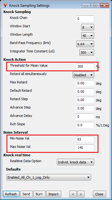
Knock sampling dialog with detect settings highlighted
Knock Detect Settings
Threshold for mean value: this is a scalar, which is multiplied by the mean value to determine knock 300% should be a safe value to start, if you want to detect knock earlier (mean based) lower this although values
lower than 250% are not recommended, valid good range 250-400%.
Min noise val/Max noise val: Values used in gain self calibration mode (currently disabled), however mean of both values is used as a low limiter for knock_mean (knock reference average value on your knock screen)
stay with the default values until instructed otherwise
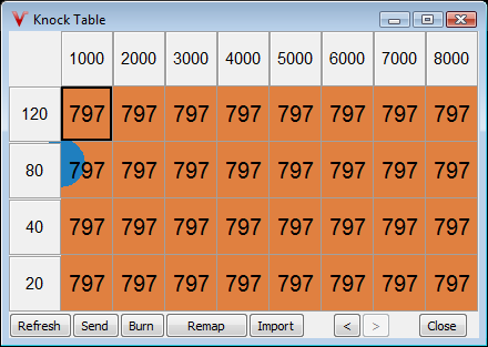
Knock noise table default
Knock Noise Table
Knock noise table: this table is used for your active noise reading (kpa/rpm based) for the current cylinder, it can be upscaled using knock_reference_value per cylinder although it is recommended to keep these 100% for
all applications. Entering a value of 797 disables knock control in this area, useful for overrun/low map or very low rpm conditions.
Knock Detection Calibration
Now that the meaning of the knock noise table is clear it is required to setup the knock noise table with measured values for your engine, procedure will be explained in a few simple steps:
- Start the engine and open up the knock screen in VemsTune/View/Group/Knock, you should see monitoring of individual knock values for each cylinder (like before during gain calibration). If you take a look at the bottom of the knock screen you will see a gauge knock reference noise. This is the gauge we will need for the setup of our knock noise table.
- Start a datalog, then sweep rpm slowly from min rpm knock noise table val (around idle) to max rpm table val (around redline) all at low/light load, than stop datalog.
- Now that we have logged our data we need to analyze it, replay log and monitor knock reference noise levels at your table rpm bin values. Now enter your knock noise thresholds into the table, for each logged knock_reference_noise add 100 to threshold in table, fill same value for entire column. Remember we want to trigger detection above noise level (hence the added 100).
- If possible make a log at full load and fill in the noise levels for the top row of the knock_noise table; using the same procedure (without setting to entire column) as before, afterwards table can be interpolated from max to min load values.
- If desired you can fill area where knock detection is not desirable with 797 to disable detection in those area's usually overrun/low map or idle
An example of what your knock noise table might look like when finished is included below
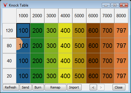
Knock noise setup example
Your Vems ecu is now properly calibrated for knock sampling and detection but does not yet act on it, setup of these parameters will be handled in the next paragraph.
Knock control action setup
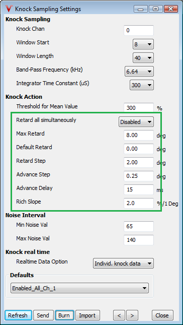
In this section we will be focusing on the settings of the advanced knock control system which are related to knock action, e.g. what happens when knock is detected.
Below you find an example of the knock settings dialog as it is available in inputs/knock sampling in VemsTune. The variables which are needed for the setup knock action are highlighted in the green rectangle.
Included are safe defaults for the knock action variables, these are also available in the default "Enabled_All_Ch_1".
Do not apply this default but manually enter settings otherwise this will overwrite your previously done calibration!
Knock sampling with updated action settings
Knock Sampling Action Settings
Retard all simultaneously: When enabled all cylinders will be retarded if one cylinder (or more) detects knock, when disabled the cylinders are retarded on a per cylinder base (requires cam sync)
Max Retard: The maximum allowed knock retard in degrees, knock control will not retard more than this even if there still is knock present
Default Retard: Default applied retard this is applied on first start, if there is no knock present it will be removed quickly, take care this also applies knock enrichment on startup.
Retard Step: Amount of degrees to retard timing (for that cylinder or all) immediately if knock is detected, will be increased each iteration if still knock and below max retard
Advance Step: Amount of degrees to advance timing when knock is no longer detected, will be advanced each iteration until all retard is removed (or knock detected)
Advance Delay: Time to wait before advancing timing (mS), will wait after each iteration for advance delay mS (e.g. advance slowly/retard fast)
Rich Slope: Applied enrichment (in %/1 degree) this acts on lambda target, when knock retard is present, lambda is corrected with retarded_degrees * this percentage. This way knock enrichment is also present in closed loop (ego ON).
This concludes your Vems ecu knock system setup. It is now properly calibrated for knock sampling, detection and action