Subpage of Base setup menu
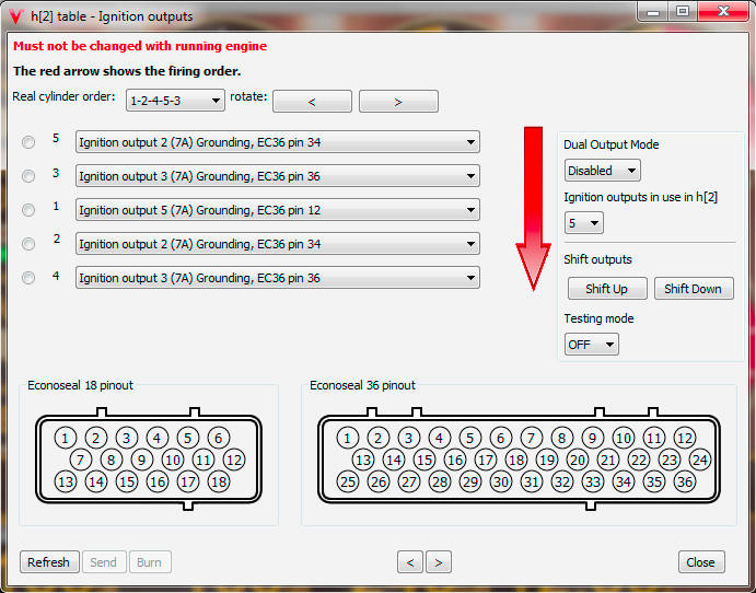
Ignition outputs visual

This example show a somewhat unusual Audi 3B (similar as AAN/ADU/ABY) 5cylinder engine with auditrigger and firing order 1-2-4-5-3 ... 5 sparkplugs on 1+2*2 wasted spark 5 cylinder engine, non-factory ignition through 3 ignition output drivers... cyl 1 alone (ignout5, actually via "logiclevel" ignition output and factory ignition Power output stage and factory ignition transformer), cyl2,5 paired (ignout2) and cyl3,4 also paired (ignout3) using aftermarket 2x2 ignition transformer (with power-IGBT outputs: that is internal drivers, not external).
Arrow shows direction of traverse. "Real cylinder number(s)", as set here, show up in per cylinder knock and individual power gauges, to show which sparkplug, sparkplug HV-wire or cylinder acts up (without looking up output => wiring each time). "Real cylinder numbers" are for display only, do not (at the time of this writing) effect spark sequence (or engine operation in any way - you can "rotate" without any effect on firing order). The chosen ignition output (and therefore "Shift Up" / "Shift Down" buttons) effect spark sequence of course.
Number of ignition outputs can be selected.
Enabling the "Dual Output Mode"
is NOT recommended unless someone really knows what he is doing and sets proper dwell value (see "Ignition settings" dialog) and makes sure
NOT to overload the ignition outputs/internal or external drivers, blow fuses or ignition transformers (coils).
Some coils will only tolerate double frequency sparks at low RPM (might be useful in some case to get engine started first, or just for limp-home),
and melt after some time at higher RPM... Active COPs are most prone to this behavior, but more rugged coils might also get damaged.
Testing mode: allows manually commanded sparks on any output (useful for testing). Beware: HIGH VOLTAGE is dangerous (potentially deadly).
Testing ignition coils only outputs short "dwell-time" long pulses: Possible to see with LED+protection (diode,resistors) or special measurement tools, but not with DVM.
Alternatively: disconnect coils (=ignition transformers, they make the high voltage, much less risky without them anyway), save config; temporarily unconfigure outputs from ignouts and configure as MISC output (one or 2 at a time) which can be inverted by 1 click (in "All outputs" menu); very easy to measure, invert, measure,... with DVM DC voltage measurement because output stays indefinitely so DVM DC will show; just make sure to upload original config or configure back manually and reboot + verify before connecting coils to prevent damaging coils.
Click the left bullet to show related connector pin graphically.