Round control loop
Subpage of Round
PID Control loops
- The PID control loop feedback signal can be chosen from several input sources ( analog, temperature, rpm, lambda, etc).
- The dialog is named "Boostcontrol" (after the first such application).
- Round V1 has only 1 PWM output pin named "boost-out".
- Round V2 has altogether 3 independent controllers, driving 3 independent PWM output (boost-out, PWM0 out, PWM4 out)
- For PID controller settings see: Boost/Idle/Lambda settings
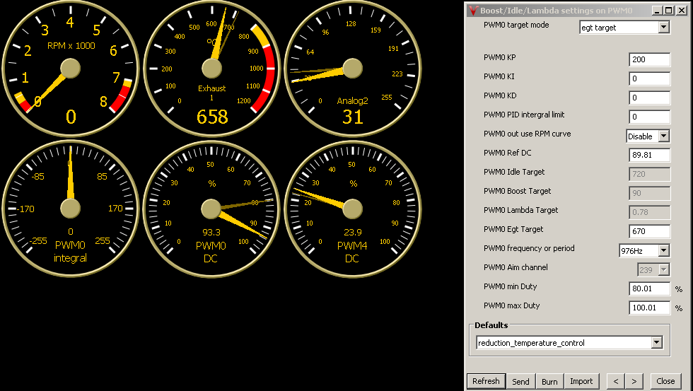
- Example Nr.:1 : Woodgas temperature control on Egt input
- The target parameters : 650 Celsius -> 95%PWM duty cycle, 700Celsius -> 80% DC with 33 seconds period time, minimum DC is 80% maximum DC is 100%
- Steps:
- Choose control unit: PWM 0,4 have configurable period, use PWM0
- Limit Duty cycle: set PWM0 min and max duty
- Select input source: Egt target
- Set target, reference DC and PID parameters
- Set Period time (note: PWM DC refresh on period ends)
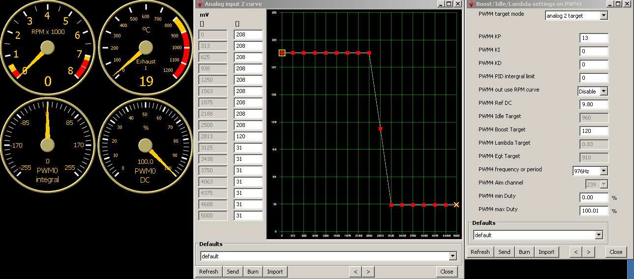
- Example Nr.:2 : Woodgas temperature control on Analog input
- The target parameters : 650 Celsius -> 5%PWM duty cycle, 700Celsius -> 15% DC with 33seconds period time, minimum DC is 0% maximum DC is 20%
- note: this example is the same as above with different hardware settings
- Steps:
- Need hardware converter from temperature sensor to analog ( Egt amplifier ) -> 650C -> 2.71V ; 700C -> 2.91V
- Choose control unit: PWM 0,4 have configurable period, use PWM4
- Limit Duty cycle: set PWM4 min and max duty
- Select input source: Analog 2 target
- Set target, reference DC and PID parameters
- Set analog 2 input curve and analog input calibration, offset
- Set Period time (note: PWM DC refresh on period ends)