Using Vemstune 1.3.1 ,VEMS 3.6 (written on the order receipt and mainboard) but Vemstune recognise it like v3.3 (firmware and bootloader is same for all, so that is OK), firmware 1.2.2.
Engine code: S50B32
Specs:
- 6 cylinder in line
- Infinite variable camshaft angle on both intake and exhaust(VANOS)
- displacement (cm3): 3201
- Stock pistons&rods , 3.5mm Cometic Headgasket and ARP hardware
- Coil on plugs and full sequential
- Stock cams
- Precision Turbo 6262turbo
- 3 vr sensors
- Crank 60-2 = primtrig
- Exhaust 6+1 Sectrig !
- Intake 6 Third trig !
- Dual Vanos Enabled
Started the engine in stock form, nothing changed, i only attached my ecu adapter socket to the car's original ecu socket.
I wanted , for the start to verify vanos functionality.
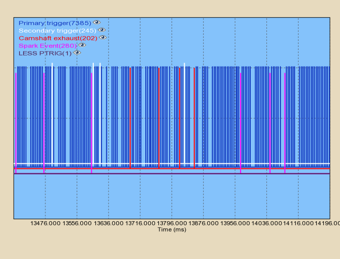
I have problems in getting a stable secondary and third trigger, also, secondary and third triggers tries to follow target cam advance maps, but not with very good success. I have manually put cams in max advance and retard position , and took note of them, after that i have made cam target maps.I have attached leds to solenoid outputs, and they are very unstable, even if in close proximity of cam target. I suspect an unstable trigger signals.
I attach two trigger logs, one only cranking and one at idle, a config file, and a log.
In the Vemslog you will see also, that around 1800-2000 rpm, i have very nasty fuelcut, i don't know the cause.
Use higher baudrate, like 115200 in triggerlog to raise the max RPM where it can capture all pulses
- even then it is limited to about 3-4000 pulses / second, so it won't capture all at high RPM: the exact RPM depends on trigger pattern
- This is a limitation of the serial baudrate (but it's perfect for starting problems and mostly also for idle if used with the right settings - hopefully your serialport handles 115200 baud, most serialport handles it OK).
-
 was apparently captured in 19200 baud (where max RPM is ~600 with a 60-2 wheel)
- in 115200 baud max RPM is several times higher
I am not very sure about VR sensors polarity, i have tried everything, and i do not have a oscilloscope to verify them.
- oscilloscope scopeshot would be highly preferrably (a borrowed scope would save a lot of time) but at least try to "PULL-AWAY METAL metal from the sensor" if possible
- measured polarity should be MINUS (DVM-DC voltage 200mV mode, black probe is the ground) normally with longgap-shorttooth wheel (the gap is longer than the tooth, or at the missing tooth the gap is enlarged)
- measured polarity should be PLUS for an inside-out longtooth-shortgap wheel (where the tooth is longer than the gap; or at the missing tooth the tooth is enlarged, not the gap as normally) - this is less common but exists
- For all 3 sensors !
Also a have seen in a DTA wiring instructions, that the Crank and exhaust cam (secondary trigger for vems) has the same polarity, but the intake cam sensor (third trigger) has inverse polarity. Can anyone confirm me that?
- When Marcell started to inspect an S50B32 (with which the main problem later turned out to be a torn crankwheel dampener resulting in trigger error and power-cut around 6800 RPM) only one of the intake or exhaust had to be inverted (but the number of previous inversions applied by the installer since the factory setup was unknown).
- to avoid any uncertainty, polarity of all 3 VR sensors should be verified individually
- Both sensors show MINUS when pulling away wrench if BLack-positive, Yellow-Negative. This is good for the exhaust cam, which has teeth (longgap-shortteeth). But the intake camwheel is different !
- the exhaust cam side has the 6+1 pattern and it has teeths
- so for exhaust cam Yellow-GND, Black-signal
- the intake cam side 6 pattern BLack-GND, Yellow-signal because intake cam has 6 gaps, not teeth (longtooth-shortgap).
- when you verify, with a longtooth-shortgap wheel you are reading PLUS with the pull-away method (when connected with good polarity)
- I must use rising edge or falling edge for secondary trigger?
- with VR sensor always configure rising edge in software (falling edge only usefuly for HALL).
- explanation: The VR chip lm1815 senses the falling edge of the incoming signal and generates a rising edge for the processor. Maybe confusing, but that's how it works
- There is somwhere good info about the settings for the knock sensing, for my firmware? I have connected two sensors, bosch with 2 wires. Connected them to pin 1 and 2 of the EC18, like shown on the note when i bought the Vems. I have ordered it with dual channel knock. The ground pin 17 is connected to sensors ground. In the settings, knock sampling, i have put KNOCK CHAN = 255 , winstart=12, winlenght= 60 , for the first channel - frequency to 6.64, gain=2, ITC=240, same for the second channel. I have tred to tap the sensors with a hammer with non running engine, and watched KNOCK DIFF gauge, nothing happens, i have tried also different settings, but no sign of life . I wil need some help in this matter.