I already have installed Genboard v3 in VW Scirocco, with 1.8 20VT engine. Lots of configuration to be done.
Previously equipped with Megasquirt v2.2 with Extra code. Continuous problems with ecu changing settings by itself. Also coil charge times were not what they should've been (difference between MT readings and reality), so fed up with melted coils.
System consists of:
- VW Scirocco GTX 16V
- Installed Seat 4-cyl 1.8l 20V turbo engine
- Vems v3.3, firmware 1.0.69
- OEM VW sensors, IAT, CLT, TPS, CamSync
- 2.0 16V VW engine Hall-sensor for primary trigger
- 60-2 trigger wheel
- Polo GTI wasted spark coilpack
- Standard 1-3-4-2 firing order
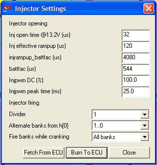
Injectors wired from A to D (will add pin#s later), configured to fire 2 banks (00..01) altenating. No sequential for now, camsync not in use at the moment. I'm trying to get the car running properly first.
Ignition coils wired to Ign00(pin35) and Ign5(pin12). Pin 12 used, beacuse for some reason, couldn't get spark from Ign01(pin33). This shouldn't be a problem, should it? These all are low level outputs anyway. Coilpack has built-in IGBTs.
- I'm working on exactly the same project nowadays - MembersPage/Fero
Here I will show my configurations for Megatune. I'll try and explain every option possible. I will update when i find answers to my own questions first. My opinion is, this Wiki is like hell to try and find something usefull. It took me more than hour to find info how to configure fuel pump output to work.
- in megatune the fuelpump output is configurable. GenBoard/Manual/DigitalOut/Table is the table most of us uses during planning (and even keeping a hardcopy during install). The EC36+EC18 pinout can be found at several places, the "external interface" of the GenBoard/Manual (see header link DocsPage)
These pages are good starting points: GenBoard/Manual and MembersPage/PhatBob/UserGuide - Mattias
ign advance - configuration or measurement problem ?
Car runs fine. If advance is forced (terminal command) to 10deg, it is 10deg. But when forced 20 or 25deg, it really is 25 or 30deg.
Here's how it went:
- set 10deg, true 1deg
- set 15deg, true 11deg
- set 20deg, true 21deg
- set 25deg, true 30deg
For 15 crankdeg ignadv command change (10..25), measurement shows appr 30 crankdeg change (1..30).
Our first guess was that something misconfigured, eg. for 2 cyl. But I couldn't spot such problem. Eg. RPM constant is 3000 (12000/4, so looks good for 4 cyl):
- rpmk[0]=0B
- rpmk[1]=B8
So it is kindof likely that using wasted spark, your smart strobe light gets confused. We've seen that happening (yes: a dummy light is often better - harder to get bad readings). Consult the the timing light userguide to investigate this.
Yes, I thought that too, but i have been measuring with this (Snap-On) tool for ages, never had any such problems before. It is a known fact though, that with this lamp, you cannot get sensible reading with advance selection at 0deg. It has to be 1 or more. I have measured dozens of VAG cars with this, including my own cars former setup with MS-Extra. I will check this anyway, maybe build a dumb-light from a bright led.
Assuming info on refcard.pdf means, mdaxx = force advance xx units, where 1 unit means 0.25deg. So 0x28 equals 10deg, 0x3c equals 15deg, 0x50 equals 20deg. => exactly. More notes:
- mda00 is special, switches off forced ignadv.set
- set ign_balance=00 while setting base timing with mda... (ign_balance only available in 1.0.x firmware, used for ALS max retard, recommended value is 20..30 degrees, but only after base timing is established).
0x50 = 5 x 16 = 80 => 80 x 0.25 = 20 deg. True. Do you have any wheel errors ? 2nd or 3rd LCD display. - Mattias
Megatune lights up a light if trigger "wheel-errors" count up to a certain number (10 or 16 or similar: might light up if engine restarted several times without ECU reboot => that is normal).
On some page was told that mlp01 takes me to the page with errors and counters, but theres just bunch of hex. W.. is the "wheel-error counter". More on [InputTrigger/TriggerLog]
Need help to translate this log-file to understandable form, anyone?
[TeroK Scirocco triggerlog 14-04-2007]
Taken with terminal program (apparently brayterm). [analyzed file zip].
perl bin/binary.pl <start_14-04-2007.bin >start_14-04-2007.txt
Looks like a 60-2 connected with good polarity. Segments like this (left side) look good (missing tooth is 3 times longer than normal tooth, actually surprisingly precisely):\n
1078    837     1
1079                                                    17667   1.04
1080    849     1.01
1081                                                    20746   1.17
1082    2561    3.01 MISSINGTOOTH 58
1083                                                    260     0.01
1084    872     0.34
1085                                                    26627   102.41 MISSINGTOOTH 11
1086    861     0.98
1087                                                    23556   0.88
1088    898     1.04
1089                                                    33283   1.41
1090    899     1
1091                                                    33540   1
1092    947     1.05
1093                                                    45828   1.36
1094    957     1.01
1095                                                    48388   1.05
1096    1013    1.05
1097                                                    62724   1.29
1098    1050    1.03
1099                                                    6660    0.1
1100    1133    1.07
1101                                                    27909   4.19 MISSINGTOOTH 8
1102    1195    1.05
1103                                                    43781   1.56 MISSINGTOOTH 1
1104    1290    1.07
1105                                                    2565    0.05
1106    1347    1.04
1107                                                    17157   6.68 MISSINGTOOTH 2
1108    1374    1.02
1109                                                    24070   1.4
1110    1312    0.95
1111                                                    8196    0.34
1112    1239    0.94
Your slowest tooth in above run is 1374 * 4 usec long, at position 1108,
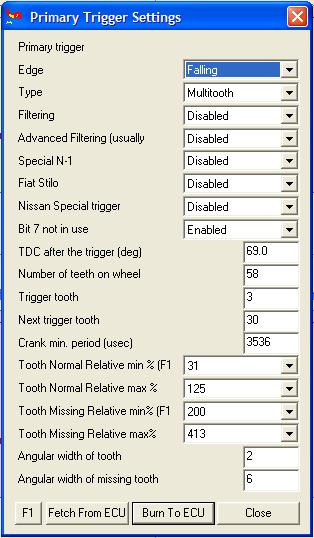
(1108 1374), that is 13 tooth after tooth0 (the first tooth after missing tooth at position 1082 (1108-1082)/2 =13). If we put trigger tooth to 03, we have appr 10 more teeth (60 crankdeg) for ign_tdcdelay (but maybe 02 is better in reality, your timing light will help):
Approximate:
- ign_tdcdelay=78 (120, that is 60 crankdeg)
- trigger_tooth=03
- another_trigger_tooth=1E (decimal 30)
So, what are those other "missingtooth" markings? Should there be just "missingtooth 58" markings, and nothing more? Does this mean there are some errors?
WBO2, strange behaviour
First wbo sensor i got, works in mysterious ways. After i got the factory settings for controller calibration, namely:
- wbo2_pump_pw_zero=0x66 (decimal 102)
- wbo2_nernstdc_target=0x88 (decimal 136)
I double checked the voltages according to PhatBob's manual. Everything were ok. When i started the free-air calibration, O2-reading swinged between 11,1 and 12%. This might be OK, depending on sensor calibration:
- sensor RCal measured resistance (between WBO2pin2 and WBO2 pin6): 125 ohm
- wbo2_calibration=BA (from mcd dump)
- wbo2_abs_limit=E0
- wbo2_limit_maxt=F0
- wbo2_fallback=70
- wbo2_retry_t=06
- wbo2_edgetime_corr=BA
- wbo2_edgetime_min=50
- wbo2_ri_target=96
- wbo2_nernstdc_target=88
- wbo2_pump_pw_zero=66
- wbo2_heater_pid_kp=46
- wbo2_heater_pid_ki=10
- wbo2_heater_pid_kd=1A
- wbo2_heater_pid_ilimit=80
- wbo2_pump_pid_kp=15
- wbo2_pump_pid_ki=4E
- wbo2_pump_pid_kd=00
- wbo2_pump_pid_ilimit=84
- wbo2_ri_confidence_scale=80
Just to make sure, i connected another sensor (from Innovate LC-1). Then it showed 20,9..21%, as it should.
- Can i assume that the first sensor is faulty?
- from this, you cannot assume. Fill in the missing data so we can help you find out.
- also, take look at (Man)mlp07
- This LCD page has many nice internal data that is useful for debugging. Eg, we can see if Ri>600 (cold sensor) which is usually caused by lack of heating, if, say, the heater is not powered - a common mistake is to try to supply power from an unsuitable node. You should also show us some of these mlp07 LCD (page 07) snapshots (mll to take one snapshot or mdf01mdk01 for continuous dump, mdf00 to switch this off).
What could be, for example, this unsuitable node?
My WBO2 supply is wired parallel to Vems supply, with own fuse ofcourse. Just like in PhatBobs manual.
- About 2mins after applying the mde02 command, couple of mlls
- Ri:0091 Nernst:10EE
- Heat:80 Pump:A5
- AFR=? 13.2
- AFR=11.58 P ON
- AFR=? 13.3
- AFR=11.58 P ON

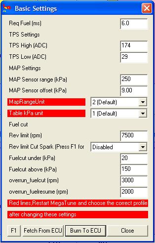
- TPS settings must be manually configured, auto cal in MT does not work
- MAP sensor settings
- The MPX4250 sensor has appr 20kPa => 0.2V and 250kPa => 4.8V, which is 230kPa/4.6V. That is 250kPa / 5V, so 250kPa is a good starting point (might slightly vary with your sensor and controller. You can calibrate, at least adjust kpa offset to get your ambient pressure reading, appr 102 ..104 kPa )
- with the 400 kPa sensor appr 20kPa => 0.2V and 400kPa => 4.8V, which is 380kPa/4.6V. 414 kPa (/5V) calibration value is a good starting point.
- with the 300 kPa sensor appr 20kPa => 0.2V and 300kPa => 4.8V, which is 280kPa/4.6V. 304 kPa (/5V) calibration value is a good starting point.

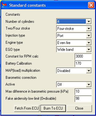
- Injection type
- Not used for control currently (could be inspected in dumps attached to requests, but requests are only considered with good project description anyway)
- Constant for RPM calc
- Whats the point in this? If needed, could be calculated internally. Found that should be 3000 for 4-cyl and 2000 for 6-cyl.
- Battery calibration, used to adjust voltage gauge to read actual supply voltage.

