I already have installed Genboard v3 in VW Scirocco, with 1.8 20VT engine. Lots of configuration to be done.
Previously equipped with Megasquirt v2.2 with Extra code. Continuous problems with ecu changing settings by itself. Also coil charge times were not what they should've been (difference between MT readings and reality), so fed up with melted coils.
System consists of:
- VW Scirocco GTX 16V
- Installed Seat 4-cyl 1.8l 20V turbo engine
- Vems v3.3, firmware 1.0.69
- OEM VW sensors, IAT, CLT, TPS, CamSync
- 2.0 16V VW engine Hall-sensor for primary trigger
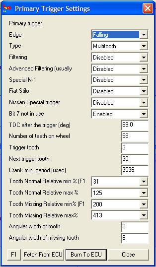
- 60-2 trigger wheel
- Polo GTI wasted spark coilpack
- Standard 1-3-4-2 firing order
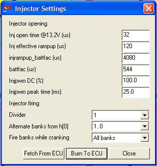
Injectors wired from A to D (will add pin#s later), configured to fire 2 banks (00..01) altenating. No sequential for now, camsync not in use at the moment. I'm trying to get the car running properly first.
Ignition coils wired to Ign00(pin35) and Ign5(pin12). Pin 12 used, beacuse for some reason, couldn't get spark from Ign01(pin33). This shouldn't be a problem, should it? These all are low level outputs anyway. Coilpack has built-in IGBTs.
- I'm working on exactly the same project nowadays - MembersPage/Fero
Here I will show my configurations for Megatune. I'll try and explain every option possible. I will update when i find answers to my own questions first. My opinion is, this Wiki is like hell to try and find something usefull. It took me more than hour to find info how to configure fuel pump output to work.
- in megatune the fuelpump output is configurable. GenBoard/Manual/DigitalOut/Table is the table most of us uses during planning (and even keeping a hardcopy during install). The EC36+EC18 pinout can be found at several places, the "external interface" of the GenBoard/Manual (see header link DocsPage)
These pages are good starting points: GenBoard/Manual and MembersPage/PhatBob/UserGuide - Mattias
ign advance - configuration or measurement problem ?
Car runs fine. If advance is forced (terminal command) to 10deg, it is 10deg. But when forced 20 or 25deg, it really is 25 or 30deg.
Here's how it went:
- set 10deg, true 1deg
- set 15deg, true 11deg
- set 20deg, true 21deg
- set 25deg, true 30deg
For 15 crankdeg ignadv command change (10..25), measurement shows appr 30 crankdeg change (1..30).
Our first guess was that something misconfigured, eg. for 2 cyl. But I couldn't spot such problem. Eg. RPM constant is 3000 (12000/4, so looks good for 4 cyl):
- rpmk[0]=0B
- rpmk[1]=B8
So it is kindof likely that using wasted spark, your smart strobe light gets confused. We've seen that happening (yes: a dummy light is often better - harder to get bad readings). Consult the the timing light userguide to investigate this.
Assuming info on refcard.pdf means, mdaxx = force advance xx units, where 1 unit means 0.25deg. So 0x28 equals 10deg, 0x3c equals 15deg, 0x50 equals 20deg. => exactly. More notes:
- mda00 is special, switches off forced ignadv.set
- set ign_balance=00 while setting base timing with mda... (ign_balance only available in 1.0.x firmware, used for ALS max retard, recommended value is 20..30 degrees, but only after base timing is established).
0x50 = 5 x 16 = 80 => 80 x 0.25 = 20 deg. True. Do you have any wheel errors ? 2nd or 3rd LCD display. - Mattias
Megatune lights up a light if trigger "wheel-errors" count up to a certain number (10 or 16 or similar: might light up if engine restarted several times without ECU reboot => that is normal).
On some page was told that mlp01 takes me to the page with errors and counters, but theres just bunch of hex. W.. is the "wheel-error counter". More on [InputTrigger/TriggerLog]

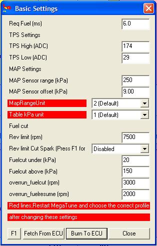
- TPS settings must be manually configured, auto cal in MT does not work
- MAP sensor settings
- The MPX4250 sensor has appr 20kPa => 0.2V and 250kPa => 4.8V, which is 230kPa/4.6V. That is 250kPa / 5V, so 250kPa is a good starting point (might slightly vary with your sensor and controller. You can calibrate, at least adjust kpa offset to get your ambient pressure reading, appr 102 ..104 kPa )
- with the 400 kPa sensor appr 20kPa => 0.2V and 400kPa => 4.8V, which is 380kPa/4.6V. 414 kPa (/5V) calibration value is a good starting point.
- with the 300 kPa sensor appr 20kPa => 0.2V and 300kPa => 4.8V, which is 280kPa/4.6V. 304 kPa (/5V) calibration value is a good starting point.

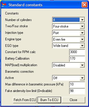
- Injection type
- Not used for control currently (could be inspected in dumps attached to requests, but requests are only considered with good project description anyway)
- Constant for RPM calc
- Whats the point in this? If needed, could be calculated internally. Found that should be 3000 for 4-cyl and 2000 for 6-cyl.
- Battery calibration, used to adjust voltage gauge to read actual supply voltage.

