This page contains all test of the new Subaru Trigger code
2010-06-01:
Conclusions so far:
- The trigger polarity is correct in all the scope shots.
- No noise is seen in any of them, but a ghost LM1815 output signal is seen in one place. This is PROOF that there IS noise in the signal. New measurements with "peak detect" active in the scope may show high frequency noise.
- This ghost output was seen with LM1815 in normal mode (pin5 left open), without pulldown and without any additional capacitors at the inputs.
- This didn't change the fact that we had misfiring when no noise was present, in later measurements(with LM1815 in 5v mode, 10n at c30 & c33 and 10k pulldown).
Goal:
We need to finalize the trigger hardware settings and verify the signals before any further trigger code development can be done.
The next step:
- Setup the trigger hardware for low tooth count VR triggers:
- Fit a pulldown with the same resistance as the trigger. If the trigger resistance is higher then 1k you use 1k pulldown!
- The trigger resistance is measured to 2k, 1k pulldown is used.
- The above MUST be combined with LM1815 mode=5v.
- LM1815 mode=5v is used
- Fit a pulldown with the same resistance as the trigger. If the trigger resistance is higher then 1k you use 1k pulldown!
- Fit new filter capacitors for improved high frequency noise rejection.
- Fit plastic capacitors instead of the ceramic ones in position C30 and C33. Don't bother with posions C31 and C34, they are not filters. I suggest Wima FKP2 2200PF 2,5% 630VDC, Elfa# 65-710-61 as those has given me very good results with the high frequency noise often found in jap cars.
- Wima 2200pF 100V plastic (red ones)is used, hope this will do.. 1nF ceramic ones is removed.
- Fit plastic capacitors instead of the ceramic ones in position C30 and C33. Don't bother with posions C31 and C34, they are not filters. I suggest Wima FKP2 2200PF 2,5% 630VDC, Elfa# 65-710-61 as those has given me very good results with the high frequency noise often found in jap cars.
Measure:
You probably need to measure with the peak detector on in the scope. Measure with fuelpump OFF but with injectors ON and ignition ON.
Measurements in order of importantce.
- Measure the signals at the connector (or any place inside the ECU before the filter)
- This is done. As seen at the shot, there is indeed noise. Most noise is seen at CH2, maybe because there was only ground wire at CH1 at this point. Peak Detect is used. Fuelpump is OFF, ignition and injector outputs is ON.
- The 3rd shot is zoomed at a noise pulse. To see more details, Peak Detect is disabled in the following measurements..
- Measure the signal before and after the filter. (At connector and at pin3 of LM1815.)
- CH1 is connected to secondary input (connector), CH2 is connected at secondary LM1815 pin3. Ground wire at both probes this time.
- Measure the signal before the filter and on the LM1815 output.
- CH2 is now at secondary LM1815 pin12. Trigger level was set to 2V so only noise pulses was captured. Cranking was done for more than 1 minute, a lot off noise pulses was seen, but not a single false output at pin12. The scope shot is the one captured with the largest noise pulse.
- If at all possible start the car and measure the primary and secondary signals before the filters.
- If any new noise is seen with the car running, measure at pin3 and at pin12 of LM1815.
- Still has to be done. Coudn't risk a misfire in the nieghborhood at this point (22:50) ;o)
- If any new noise is seen with the car running, measure at pin3 and at pin12 of LM1815.
With the peak detector active in the scope you should not need the pulse extender, the signal at pin12 should be captured easily. If you can't capture that pulse you need to review the scope settings, otherwise it will not be able to see the noise in the signal!
Jörgen
- Subaru Trigger test 2010-05-25 to 2010-05-29
List of essentials - none met yet ?
- firmware ? 1.1.75 or 1.1.77 ? (there is no chance at all with ''1.1.76)** 1.1.74 is used
- vemscfg and vemslog ? **Peter will guide you
- triggerlog ?**Peter will guide you
- analog DC voltage on the trigger inputs (both primary and secondary). Ignition on, but engine off is OK.
- how did you make sure about the polarity of both VR signals ? ** from manual, but also scope
- the ECU must see falling edge on the input, as per the LM1815 specs!** It is the right way
- scopeshots if possible ** Peter will add them tonight
- but scopeshot is likely only partially useful with 5 ksample / seconds. (at least we can verify the polarity though)**
We have observed misfire at every attemp to start engine, even though correct output from both LM1815 has been measured several times. Therefore this problem have to be fund in the firmware. Other problems like rpm signals up to >50000 rpm (without 2x10nF at inputs)and misfire above 2500 rpm, could still be due to hardware. will have to do some more measurements to verify that.
- We've seen 1..2 usec offensive pulses capacitively charged from the ignition of a Nissan (of a certain harness: 40 other working well without this problem). Since that was HALL, we could solve it in software with the HALL-dirac filtering and the customer was very happy.
- With VR the same software solution is not possible, as the LM1815 hides the characteristics of the input from the processor. So with VR the triggering must be solved reliably in HW, but still without noise.
- There is obviously a narrow range of values for auditrigger and subaru (and low toothcount VR in general). But just like auditrigger was solved (and now only 1 in 40 audi needs special attention beyond the normal procedure) the Subaru will be solved too.
The amount of work and chit-chat is fruitless without these rudimentary information. Another problem might be that the primary and secondary might require different pulldown/up values. If the VR polarity is wrong, it might be extremely hard or impossible to get it working properly. (just because it starts one way and not the other - with a certain pullup - does NOT mean that one way is good polarity !).
VERY IMPORTANT: If it turns out that you have very high frequency noise bursts it has very recently become clear that the very high performance ceramic capacitors we use are not optimal in the 1 MHz range. The datasheets fail to explain this so far. The reason for the behavior is so far unknown but practical tests and measurements show a huge difference between the ceramic and plastic caps at 1MHz in our application. -Jörgen.
I have had great success with polyester capacitors in the C30 and C33 positions on two cars with this type of noise, 2nF should be enough, I use: Wima FKP2 2200PF 2,5% 630VDC, Elfa# 65-710-61. I see that you have changed the capacitors in the C31 and C34 positions, these are NOT filter capacitors. They time the pulse from the LM1815. - Jörgen.
- Note. Scoop images will come in a few days
Trying to find the Subaru trigger problem while cranking, i have done some measurements.
My cheap, only 2k$ Agilent DSO3062A oscilloscope, does only have a sample rate of 1 to 5 kSa/s when measuring
over these relatively long times.. :o(
- The pulses at LM1815 output is default 25 micro sec.
- To reliable capture any pulses at LM1815.12 I have therefore
NewFile_00:
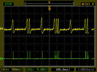
Measurements at secondary trigger.
CH1 at LM1815 pin3
CH2 at LM1815 pin12 (extender between)
Cranking at approx. 150 rpm
rpm signal in VemsTune jumps time to time to 170 rpm
Fuelpump off
NewFile_01:
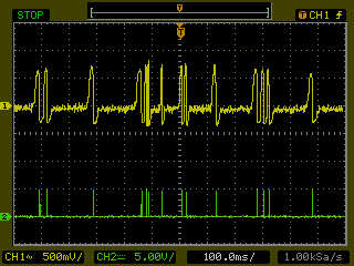
Measurements at secondary trigger.
CH1 at LM1815 pin3
CH2 at LM1815 pin12 (extender between)
Cranking at approx. 150 rpm
rpm signal in VemsTune jumps a lot
Fuelpump on
mis/backfiring!!
NewFile_02:
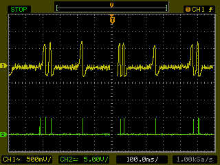
Measurements at secondary trigger.
CH1 at LM1815 pin3
CH2 at LM1815 pin12 (extender between)
Cranking at approx. 120 rpm
rpm signal in VemsTune jumps to 170 rpm, at the exact time the noise pulse is seen at the scope.
Fuelpump off
NewFile_03 to NewFile_05: (Different zoom's at the same shot)
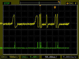
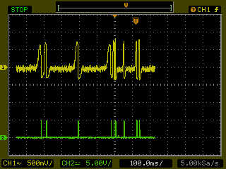
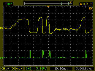
Measurements at secondary trigger.
CH1 at LM1815 pin3
CH2 at LM1815 pin12 (extender between)
Cranking at approx. 150 rpm
rpm signal in VemsTune jumps time to time to 3000 rpm
Fuelpump on
pin5 is now tied to Vcc. This has resulted in no noise at pin12, but still misfiring..
NewFile_0A
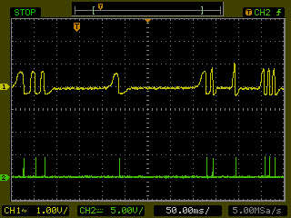
Waveform 1.
Measurements at secondary trigger.
CH1 at LM1815 pin3
CH2 at LM1815 pin12 (extender between)
Cranking at approx. 150 rpm
rpm signal in VemsTune jumps time to time to 3000 rpm
Fuelpump on
pin5 tied to Vcc
10nF at C31, C34, C30, C33
Log 21.24.17
NewFile_0B
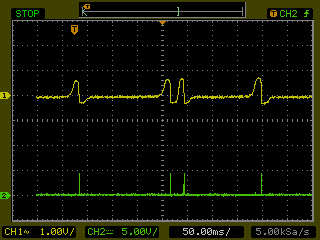
Waveform 2.
Measurements at secondary trigger.
CH1 at LM1815 pin3
CH2 at LM1815 pin12 (extender between)
Cranking at approx. 150 rpm
rpm signal in VemsTune jumps time to time to 3000 rpm
Fuelpump on
pin5 tied to Vcc
10nF at C31, C34, C30, C33
10k pulldown at both trigger inputs
Log 21.55.45
Log 22.01.02 Ignition lock 15_degrees
NewFile_0C & _0D
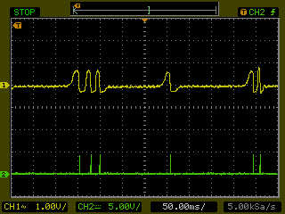
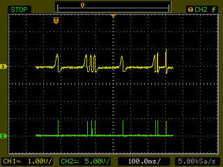
Waveform 3.
Measurements at secondary trigger.
CH1 at LM1815 pin3
CH2 at LM1815 pin12 (extender between)
Cranking at approx. 150 rpm
rpm signal in VemsTune jumps time to time to 3000 rpm
Fuelpump on
pin5 tied to Vcc
10nF at C31, C34, C30, C33
10k pulldown at both trigger inputs
NewFile_0E & _0F
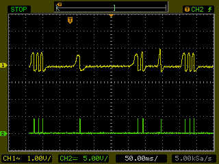
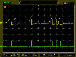
Waveform 4.
Measurements at secondary trigger.
CH1 at LM1815 pin3
CH2 at LM1815 pin12 (extender between)
Cranking at approx. 150 rpm
rpm signal in VemsTune jumps time to time to 3000 rpm
Fuelpump on
pin5 tied to Vcc
10nF at C31, C34, C30, C33
10k pulldown at both trigger inputs
Ignition lock 15_degrees
NewFile_10 & 20 (_10 waveform at USB)
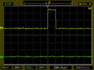
To verify that there is correct signal from both LM1815.12.
Measurements at primary and secondary trigger.
CH1 at LM1815 pin12, primary
CH2 at LM1815 pin12, secondary
Fuelpump off
NewFile_30, 40, 50 & 60 (Same scope shot, different zoom's etc.)
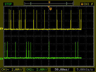
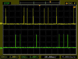
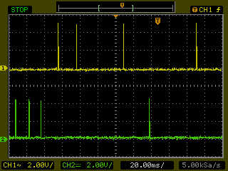
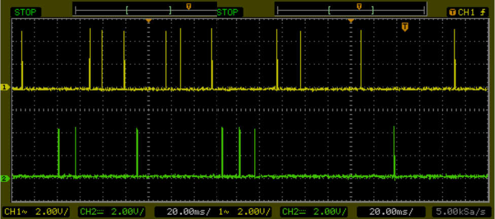
Waveform 5.
Measurements at primary and secondary trigger.
CH1 at LM1815 pin12, primary
CH2 at LM1815 pin12, secondary
Fuelpump on
Misfiring
After varming up the engine with old ECU, it's possible to start the engine
with VEMS ECU.
At this time the engine cranks at approx. 200 rpm. A short misfire at startup,
but the engine overcome this and starts anyway.
When the engine revs up, misfire apears above approx. 2500 rpm.
Trying to avoid this problem, i removed both pin5's from Vcc.
Logfile 18:00:10
Trigger log 18:00:52
Didn't chance anything
2 x 10k pulldown is then removed.
Didn't change anything
2 x 10nF at input's is then removed
Now the engine can't start at all. Misfires and rpm in Vemstune jums to > 50.000 rpm!!
You need to add capacitance
- eg. 100 nF onboard after the 10k
- and possibly 220nF or 470 uF before the 10k - that is right on the input
2 x 10nF is mounted again, and we are back to a working system when the engine is hot,
and the rpm is kept under 2500 rpm.....
Ole Blach 2010-05-30
Hint: please route the trigger signals and trigger GND in a separate cable, shielded on one side. There is no substitute for this test. If that works to prevent ign noise sneaking into trigger, it gives a huge help even if we must be able to use the factory harness in the end (likely with higher input capacitance values).
28/5-2010
Did some more test today.
Status car is not running.
All test results will be published Saturday
Scooped signals to the processor and did not find any thing wrong.
Stable rpm until it starts to fire then rpm spikes to 3000 rpm. Symptoms like the old trigger setup.
When the engine starts to run fast it looses sync.
What we have seen 2010-05-24
We have stable 160 rpm at cranking fuel pump off.
When we cranking the car it´s stable in beginning it fires up to 300-600 rpm then random fires and rpm is no longer stable.
Its like it runs only on two cylinders (firing correct) but then losing sync.
We see some correct firing´s but also ignition fires at different times than it should. Obviously there is noise in the signal, that must be filtered.
Question: Haw is this code tested and what signal is used?
- It is very important when testing that we have a swinging signal like 100-300-120-500-200 rpm`s and not lousing sync. Not joust a long stable sweep
- yes, it is tested with sweeping signal
We have big trouble scoping the output of LM1815 because of the short signal like 15 micro sec. It should be a bit higher (20-30 usec), but you can enlarge it very easily, see below.
I would suggests that we use the p259 led´s output. When the processor get signal from lm1815 Pre/sec trigger we set the output high for 0.5 sec. This will give us a chance to see and measure what goes in and out of lm1815.
Triggerlog also shows the time of the pulse (although currently for the primary trigger only).
Watching the input with analog scope is of primary importance. Even if the output is perfect, if the input is on the edge, it can break any time (eg. in cold).
Analog scopeshots ? do you have some ?
http://www.syvecs.com/forum/viewtopic.php?f=6&t=110&p=474&hilit=trigger+pattern+advisory+note#p474
If the input is biased properly, the LM1815 adaptive filtering should filter out small amplitude "phantom-tooth" pulses in the subaru. I didn't see your scope so only you can judge the offending amplitude. 10-30% should not trigg, and with lower R181 / R182 even higher amplitude offenders can be filtered out
Maybe the noise is capacitively injected by ignition ? It could save a LOT of time (even 1 week) to route the VR signals via properly shielded cable (with ground wire inside, and shield connected to ground only on ECU side). Than only try the factory harness when it works well with the separate shielded cable so you have a good starting point reference.
Ideas - setting up more agressive filtering for this low toothcount
- the LM1815 (especially for the primary trigger) is set up so it can receive 9000 RPM signal from the audi 135 tooth. As subaru has only 6 teeth (the shortest gap is 30 degrees which is equivalent to 12 teeth) the circuit can be modified for 10 times higher times.
- 10 nF => 100 nF on the input
- 1nF => 10 nF for the output pulse timing
- please verify the above values (I wrote them from memory), and multiply with the accompanying resistor so 3*R*C is less than 30 degrees
- LM1815 mode pin5=5 can be tried (and left it open can be tried too). Often used with 1k pulldown in audis for the low toothcount crankhome-VR.
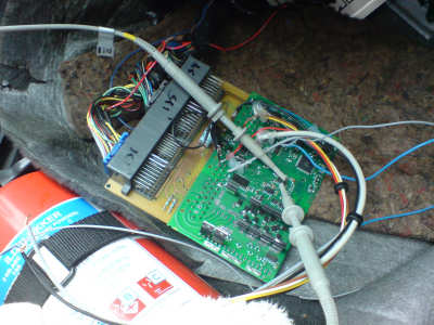
New Vems pcb installed
Our technical engineer trying to hunt down the errors
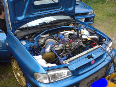
Test car 600 Hp HKS Subaru
Subaru / fiatstilo code
- Unlike in 1.0.x where the subaru was a special case of the missing tooth type,
- in 1.1.7x it's devised from the N+1 type (which is well proven also, eg. 12+1 is very common in Jap engines).
- do we suspect that RPM variations during cranking are so severe (RPM *= 1.5 in just 90 degrees) that in the 60,90,30 train the 90<60 and therefore misdetected as the "short pulse" ?
- if yes, we can possibly solve that with code modification tooth_relative_length(p16, etime_atp/2); so setting 120% threshold actually means 60%
- note that it can work either "missing tooth advanced filter bit" = 0 or 1 (trigger_multitooth_hairy is bit3)
- however, the minimum for TOOTHREL_SINGLE is currently 100% (while 60% with the suggested mod might provide better margin)
- either scope or triggerlog should reveal this. Note that this cannot possibly cause anything at 2000 RPM (such extreme *1.5 between 2 teeth) relative accelerations only happen during cranking
<pre>
if ( config_primary_trigger & _BV(ptrig_coil)) { // even (coil) type trigger
// LANCIA_COSWORTH does NOT need toothlen examination (only campulse "shaping" elsewhere)
if( FIATSTILO_SUBARU ){ // toothlen examination (and tooth skipping => c004 trigger)
uint16_t etime_atp;
etime.ptrig_capturedtime_prev = capturedtime;
etime_atp = etime.average_tooth_period;
p16 = (lsr16(period32) == 0) ? (uint16_t) period32 : 0xffff;
etime.average_tooth_period = p16; // store new period
if( (config.primary_trigger & _BV(trigger_multitooth_hairy)) == 0 ){ // no advanced missingtooth filter
if( p16 >= etime_atp ) return; // goto trigger_filter does not work well (as is) for SUBARU anyway....
} else {
// uint8_t tooth_cnt = etime.tooth_cnt;
// Looking for appr 30% relative toothlen (15..60% would be cool). Definitely skip any >= 100%
uint8_t toothlen = tooth_relative_length(p16, etime_atp);
if (toothlen != TOOTHREL_SINGLE) return;
}
// We are at the "trigger tooth".
// help initial sync a bit ? Maybe more sensitive than the simple coil type pattern.
// let's see if we had enough camsync pulses (eg. 3 needed in subaru)
if (engine.strig_count >= config.another_trigger_tooth) engine.status_trig |= cam_sync_mask;
// if > than fire some sectrig error flag ???
engine.strig_count = 0;
}
</pre>