| [Start] | [Questions ] | [ Injector] | [Ignition] | [Triger] | [Display] | [Wbo2] | [Config] | [Table] | [Wiring] |
Display
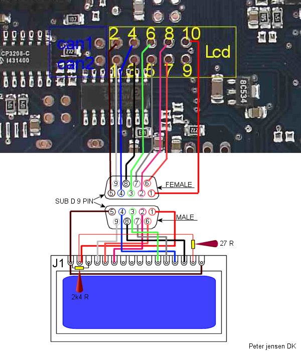
Q: Which resistors did you use? Is this similar to the green LCD screens?
- Typically 2k2 .. 2k4 ohm resistor between LCDpin1 (GND) and LCDpin3 (Contrast) (best value may vary, adjust)
- If the display is unclear trial to change this up/down (or first use a variable R, and adjust to best contrast, than remove the variable resistor and measure it's resistance)
- Connect a 27..100 ohm resister between bin 2 and pin 15 Backlight+
- Connect pin 1 and pin 16 Backlight-
That should work…
see also http://www.vems.hu/wiki/index.php?page=GenBoard%2FBuildProcedures%2FLCDconnect
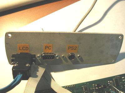
PLEASE NOTE THAT STANDARD is DSUB9 male=LCD conn on ECU (and DSUB9 female is ECU RS232 so a male USB-RS232 can be plugged into ECU RS232 but NOT the LCD !), drawing below suggests nonstandard opposite sex


