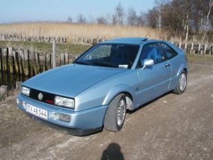
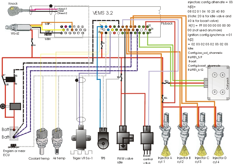
I am starting building the VEMS board for my Corrado g60 turbo.
Corrado 1989
1800 ccm
Turbo Garret T3 60 trim
Mail: motor at webspeed.dk
| [Start] | [Questions ] | [Injector] | [Ignition] | [Triger] | [Display] | [Wbo2] | [Config] | [Table] | |
| prob. rpm | 9250 | 9000 | 8920 | 8780 | 8560 | 8320 | 8259 | 7630 | 7270 |
[http://www.vems.hu/wiki/index.php?action=edit&page=MembersPage%2FPeterJensen
MembersPage/PeterJensen/Questions
MembersPage/PeterJenseninjector
MembersPage/PeterJensenignition
MembersPage/PeterJensentrigger
MembersPage/PeterJensenDisplay

Problems
- serious: "injector common" (inj +, red) must always (even if all fuses break!) be connected to the flyback rail. Flyback rail is normally EC36-pin23, but might be EC36pin22 in your case if you assembled the ECM and chose to connect the airwire to EC36pin22. A quick DVM measurement in diode mode will tell: injector output to flyrail is appr 600..1100mV.
- minor: knock shield should be normal GND, not GND5
- Q. Coolant temp questions? Is ET possible to changes the limit of temperatures from 110 degrees to about 140 degrees. My Corrado is running 120 Engine Coolant Temperature max load so ET is out of limit
It seems this will be needed sooner than later (the traditional megasquirt definition still in use is very bad, -50..+205C would be more appropriate to fit aircooled), it involves several things:
- example for matfactor and airdenfactor inc files. Recompile firmware with changed tables of your choice, and you have extended range immediately. To get good reading in megatune, you also need:
- redefine engine.coolant with extended range
- documentation issue
- LCD display
- MegaTune
- Q. Haw to connect the knock sensor ? Direct on the board TopLeft 3-holes centre is -.

- EC36pin5, EC36pin21 and EC36pin32 are all the same ground (GND5), where all "output"-transistors are mounted to (= noice/disturbances). Ground to sensors should be connected to EC36pin26, where the ECU are mounted to, and so close to the battery as posible to avoid noice. Regards HansK
- Note that the sensor GND (EC36pin26) should be used for sensors instead of the powerGND
- showstopper for trigger
- showstopper for knock
- serious TPSdot noise on TPS (TPS-accel engaged unintentionally)
- some measurement error on temperature sensors
- Make your wiring with Corel Draw just download the [cdr file]
- VERY important: the current that goes to the powergnd pins (=GND5, that is EC36pin5, EC36pin21, EC36pin32 and often EC36pin22 is also used for GND5, when EC36pin22 airwired inside the ECM to GND5 plane) must NOT effect the sensor-GND. That suggests to use separate wireS (yes, not one but 3..4 wires as independent as possible, only connect very near the battery), not sharing path with sensor-GND.
Need help for Wbo2
When I issued the command “Manmde02”, the heater turned ON but it seemed to turn OFF again after one scan. The problem was: 1A supply was too weak
If the supply is too weak:
- GenBoard might reset. The uptime seconds counter (that is seen eg. in MegaTune) resetting to 0 shows this
- or possibly, if the sensor is not heated in a reasonable amount of time, the heating decays to wbo2_fallback for wbo2_retry_t time when the heater PID controls takes another chance. La:??.? should be displayed when the heater does not reach target.
If you want to tweak the settings, check the following config variables:
(copied from global.h, the firsthand source of variables)\n
  uint8_t wbo2_limit_maxt;     // wbo2, max time spent at abs_limit [262msec]
  uint8_t wbo2_fallback;     // wbo2, fallback V after maxt [1c=10V ff=30V] ... actually this comment is bogus, FF is 100%
  uint8_t wbo2_retry_t;     // wbo2, retry control after [4sec]