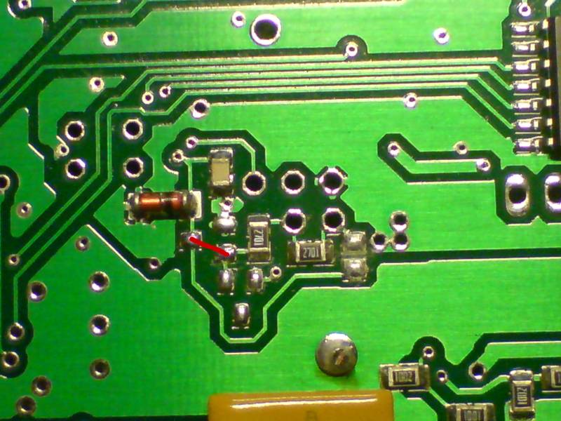
vems 3.7 board vr/vr setup
need changing over to vr/hall
engine BMW m50b25tu
- primary trigger=VR 60-2 crank
- R30=18k (but 10k or 27k should also work). You probably do NOT want to change anything around primtrig, since primtrig=VR already (1k would be too strong anyway)
- secondary trigger=HALL sensor on cam
- Changing to HALL should be simple, see GenBoard/Manual/InputTriggerHardWareSectrigHall
bottom view
https://drive.google.com/open?id=1eMa0XuRHrnh7cIYlCcI1ERID85F0nHxQ
top view
https://drive.google.com/open?id=1HEHAyxgnL-CFirkSctx10CqGjVuHbLED
- I understand that the sj7 which is closed need to be opened
- yes, unsolder
Also: apply the short according to small slanted line

My image looks diff at this point:
https://drive.google.com/open?id=1WQ8ZMNXJSmv1sGjeOYzjHtMW9af0N-gW
- Of course different, because yours is configured for VR
Recommended mod:
- the manually SOLDERED 2k7 (2701) resistor must be removed ( on your pic: at 4 hours from the southern end of hotmelt)
- R48 must be installed (input signal pullup: 2k7..4k7)
- some hotmelt seems to be over the most convenient place for sectrig input pullup, remove southern end of hotmelt before soldering
- soldering the removed "2701" 2k7 resistor could work if not damaged, but the rescuekit (small bag included with devices) should have new resistors
For the curious, About the other 5 holes:
- there is a red wire attached at another point on the bottom
- do i just disconnect it ?
- goes toward LM1815 pin3, should not matter. I would leave that, do the above mods, and test that way (remove if necessary, or cut+insulate or cut both ends, but it should not matter).
- actually, if you're absolutely certain the HALL sensor output is 0/5V (not 0/12V, but usually HALL output pulls to GND which is fine, even if HALL sensor is powered from 12V) the simplest hack would be to cut the northern end of red wire, blank it a few mm, and connect it to the 5V1 zener (SOD-80, left on your pic) stripe-marked cathode (or SMD pad under the cathode; trace goes to processor pin). "2701" should stay in this case (act as a pullup resistor, even if not originally ment as input pullup)
- This hack bypasses input protection so not normally done: the above recommended mod is better if possible (you have an SMD or throughole resistor 2k7 .. 4k7)
First input tests:
- input disconnected: DC voltage measured >3.7V
- 1k between input and GND (instead of HALL sensor), DC voltage should measure: between 0.5V and 1.5V
Than verify in InputTrigger/TriggerLog
done as per pic
moved the resistor so it looks as above
connected the red line in the above pic
got 5 v at signal and verified it by putting 1k resistor between signal and supply and got 1.5 v
thank you
done the wiring, connected the pc using a usb ftdi cable, updated the ini files on the software then i have done the wiring according to the vanos in
http://vems.hu/download/v3/Motronic88/325-M50-vanos-and-nonvanos_OBSOLETE.xls
and used
http://vems.hu/download/v3/Motronic88/base_M50_vanos_1.2.31.vemscfg
the car is a 92 m50 i imagine it has vr primary sensor
which according to above pic my ecu is vr primary(how do i confirm on car )
on the primary trigger there is 3 pins 3 wires
i have connected the yellow wire to ec36-27(thats the only sensor connected) and connected the black and shield to same ground. when i power on just ecu to record trigger log it says no inputs connected
ec36-27 shows 5v out
the crank sensor reads .519 KOhms across signal and ground so it is working.