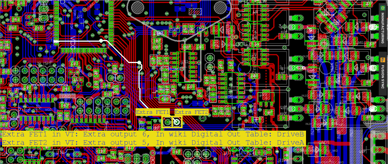
I would like to add 2 Extra NFET to V3.8 for Idle control valve
Any circuit diagram how to connect the FET's?
If you have some idea, take note about it and ask for review.
If no idea, don't do it.
Otherwise connect NFET like the other NFET-s : see GenBoard/VerThree/Schematic
- gate resistor 1k (max 2k7)
- Source = GND
- Output= Drain, with flyback diode (SMB or BY399), diode cathode = flyback return (EC36/23) (or +12V)
Possibly gate controlled from v3.8 Extra Output 5/6 :

Previously (v3.7 had) onboard provision for DPAK FETs driven from these signals (drain connected to EC18/pin6 and EC18/pin12), but flyback diode was still needed.
controlled by
- S259 ch1 see above
- S259 ch2 inverted ?
- That is what you mean ? The above is non-inverted (output active when activated)