IMPORTANT:
- I-button reader case must be GND (not +5V !!!)
- the middle pin is EC18/pin16 (that is OK).
- note: separate LED with series resistor (eg 270 Ohm) can be driven from p259 output (configure in Output/"Warning light")
- unfortunately the I-Button reader built-in LED is internally connected to GND, therefore cannot be driven from P259 output (that also pulls to GND)
It's full original, rebuilt JN 9:1 NA 1.8 8V block with 2.0 ABK head with a TD04-15T turbo.
I made a 100% new harness.
Schematic diagram:
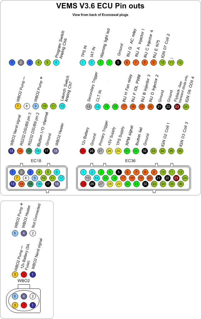
Pinout:

Primary trigger
- home-made 36-1 VR
- teeth gaps are appr 3-4mm
- very likely tooth before and after the missing tooth is much higher amplitude then other teeth
- unfortunately ECU was not ordered for poor-VR (R181 standard, not 270k). If pulses miss out (possibly only at higher RPM), remember this. Next time use HALL when making trigger at home.
- note: MembersPage/Norbitron/Audina/Quest is unrelated