Engine: Lancia Thema 2,0 16V Turbo (834 C 1.000)
Same engine type like all Fiat group 16V engines.
(Fiat Coupe,Tipo,Tempra,Croma,Lancia Delta,Thema,Kappa,Alfa 155 Q4) Engines are different only in electrical components and some mechanical details.
- Displacement: 1995ccm
- Bore: 84mm
- Stroke: 90mm
- Cilinders: 4 in line
- Firing order: 1-3-4-2
- Distribution: by belt, DOHC (2 cams in head)
- Rotation: right
Engine tuned parts:
- Turbocharger: Garrett GT3076R, (internal wastegate), assumed pressure: little more than 2 bar
- Throttle butterfly: Jaguar 4,0L, Diameter: 73mm
- Exhaust manifold: tubular type, diameter of each pipe: 42mm
- Intercooler: Water to Air type
-car will be used for DRAG RACING ONLY
Engine sensors (which will be used in my project):
Crankshaft (Trigger 1):
-pulley(Crank): 60 teeth -2
-sensor type: VR (Magneti Marelli SEN 8D - 700 Ohm) from Lancia Delta/Escort RS
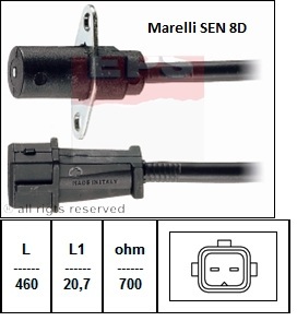
Camshaft (Trigger 2):
(if using wasted spark - dont need trigger 2)
- pulley: 1 tooth
- sensor type: HALL( Bosch 0 232 103 039) from Fiat Punto,Doblo,...
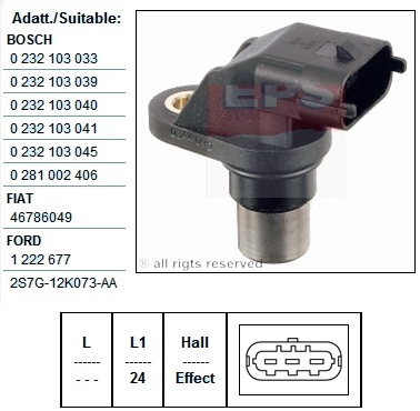
- if you have the option, HALL sensor is a better choice than VR, because low toothcount VR sensors are more sensitive to signal conditioning (pullup, pulldown) and noise
Throttle position sensor (TPS):
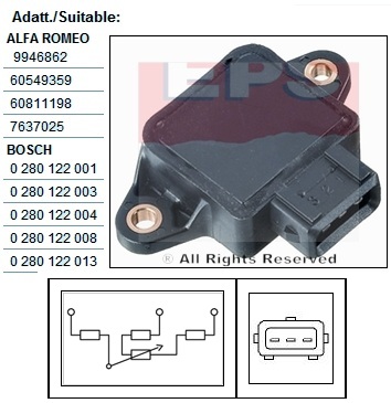
-type: Bosch 0 280 122 001
-total resistance : cca 2 kOhm
-number of wires: 3
-rotation: optional left or right (only need to swap wires)
Water temperature sensor (WT):
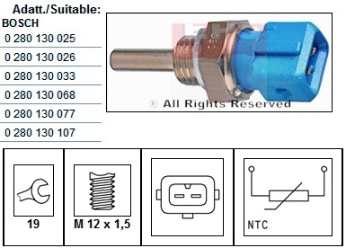
-type: negative temperature NTC (appr. 2252 Ohm at 25°C)
-mark: Bosch 0 280 130 026
-impedance at -10°C = 9 kOhm
-impedance at +20°C : 2,5 kOhm
-impedance at +80°C : 0,3 kOhm
-voltage: 5V
-number of wires: 2
Intake Air Temperature sensor (IAT):
-type: negative temperature NTC (appr. 2252 Ohm at 25°C)
-mark: Bosch 0 280 130 060 ( from Lancia Kappa 2,0 16V Turbo)
-impedance at -10°C = 9 kOhm
-impedance at +20°C : 2,5 kOhm
-impedance at +80°C : 0,3 kOhm
(this values are only informative, because i cant find values for this specific sensor - but i will measure it)
-number of wires: 2
Manifold Absolute Pressure sensor (MAP):
-VEMS internal MAP sensor (On-Board)
-Max. pressure: 400 kpa
-Voltage: 5V (or 12V)
Knock sensor:
Option 1:
-mark: Magneti Marelli SEN 14B
-operation frequecy: 12-16 kHz
Option 2:
-mark: Bosch 0 261 231 006 (usualy used by VEMS)
- Knock sensing is not perfectly implemented, and i don't recommend using it for now, but stock sensor should work once the functions is good.
Lambda sensor (O2):
-type: Wideband (5V)
-mark: Bosch 0 258 007 351 (recommended by Vems)
-number of wires: 5
Exhaust Gas Temperature sensor (EGT):
- type: VEMS
- diameter: 6mm
- without amplifier. VEMS ECU (if chosen with 1 or 2 EGT inputs) does NOT need external amplifier. For VEMS v3, external amplifier only needed for more than 2 EGT inputs. Other (non-VEMS) ECU-s that lack K-thermocouple inputs (but have 0-5V or 0-10V input) need external amplifier for K-thermocouples
Engine actuators (which will be used):
Ignition:
-wasted spark type with 2 coils
-Coils type: Marelli BAE 800B (060708038010) (Fiat Punto,Coupe, Lancia Delta,Thema,Y,...)
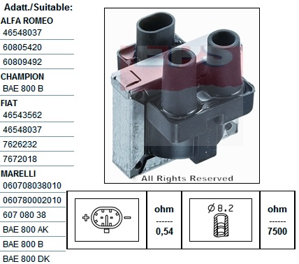
-Primary coil resistance: 0,54 Ohm
-Secondary coil resistance: 7500 Ohm
-Spark plugs: NGK BP6ET (3 electrodes in circle)
-- I would do BP6 or 7ES instead, plain copper electrode, regap to 0.4mm. (will see...)
Injection:
-Injectors type: Peak & Hold
-Number of injectors: 4
-Resistance of 1 injector: 2,5 Ohm @ 68F
-Injectors mark: RC Engineering, 750 cc/min @ 43,5 PSI
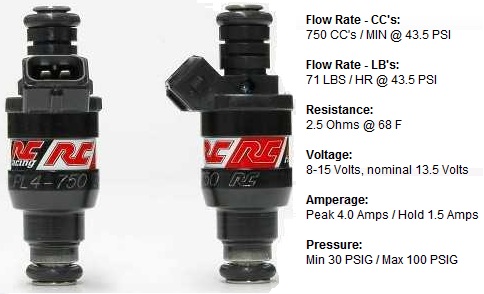
-Injectors drivers: one driver per one cilinder
-Additional series resistor for injectors: OEM type, cca 7 Ohm per each inj. (for higher flowrate, eg. 1200-2400cc low-Z injectors, the [low-Z extension 4channel] would be better, but at 750cc/min (where idle pulsewidth not extremely short) the gains are negligible compared to the simpler series-resistors
So, with an ECU with lowZ-extension (4channel)
- allow you to configure injector PWM-ing (settings appr. 1 msec, 40%) and remove the series resistors
- you can still use the series resistors if you like (than injector PWM-ing settings 25.5 msec, 100%)
- I would choose the low-z drivers anyway, they allow you to choose either method
-Fuel pump: Bosch 0 580 254 044
-Fuel pressure: 3-5 bar
Boost Control Valve:
-for this time unconnected...after: OEM Solenoid Bosch or Pierburg or VEMS
- We now have [a new solenoid] in stock, higher flow
Display:
- VEMS LCD Display (green)
Note from support crew: You've made good plans, and a nice description of your project, include the page URL in your order comment and negotiate some discount for v3.
Note from Tomas to support crew: Thank you very much support crew! ;)
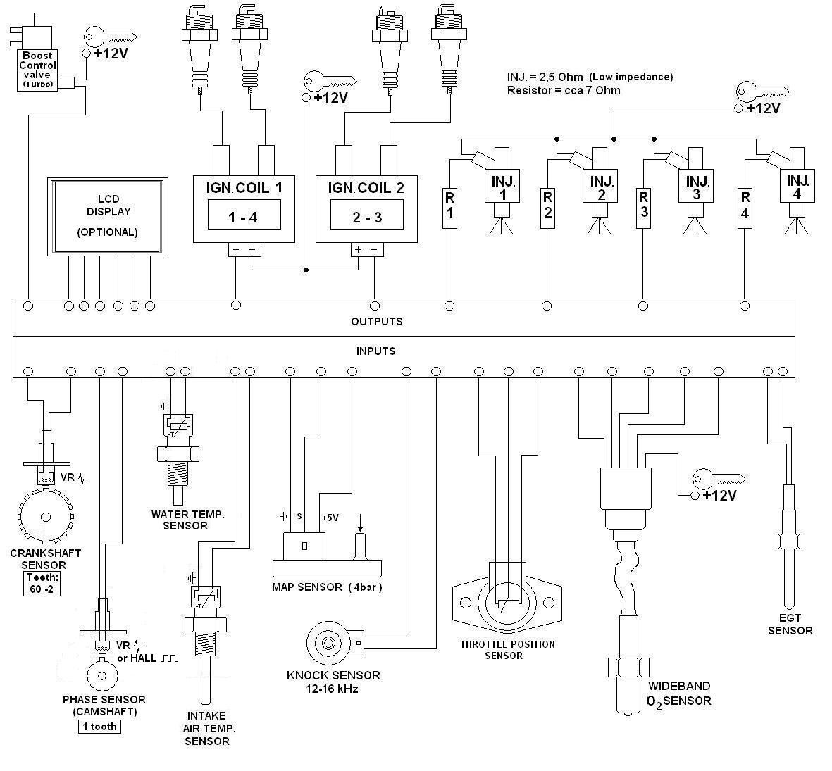
Here is my project car (the white one), which actualy runs with Lancia 2,0 16V Turbo engine with stock ECU and it is tuned for 290HP and 400 Nm. I hope with VEMS it will be better :)
This is actualy result without Vems (for this time):
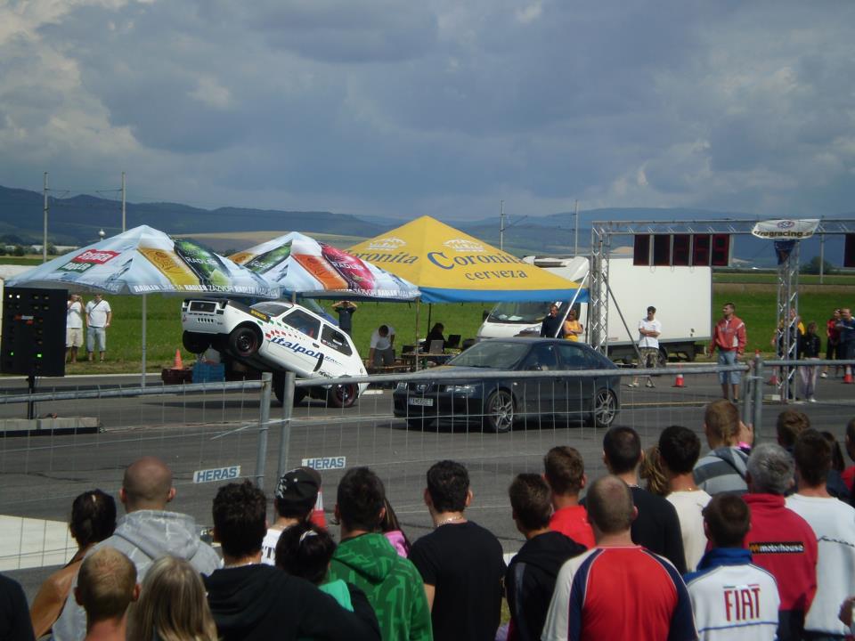
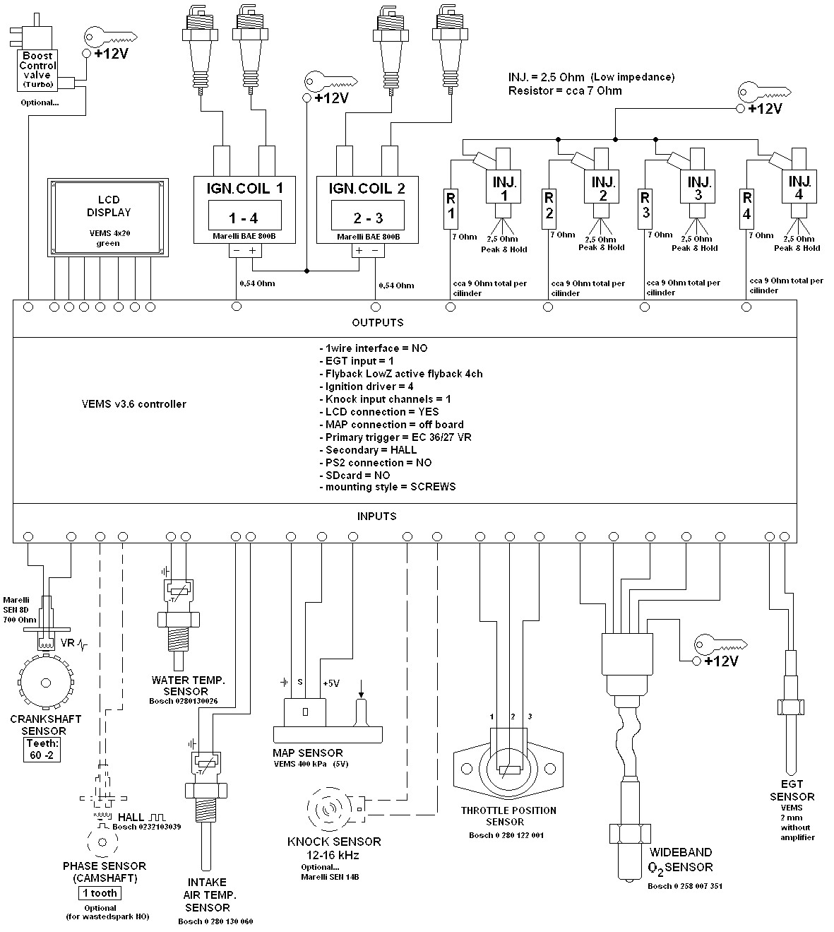
This is the current wiring diagram with a description of all components and also with the selected configuration of the VEMS V3.6 controller.
Please support crew, control if it is correct (because i want to order this configuration soon)and try to add numbers for pins (circles at the picture) for the correct connecting of VEMS v3.6 to all sensors and actuators. If it is possible, please, redraw this wiring diagram with recommended grounds connections and power supply connections. Thank you very much. Tomas.
Injector group table (for NON cam sync):
Use diagonal (top-left to bottom-right) instead (as default), and wire injectors in according order:
- injA EC36/7 cyl1
- injB EC36/19 cyl2
- injC EC36/8 cyl4
- injD EC36/20 cyl3
Note the arrow in the injector output visual group points up.
- I set the PWM-ing 40% and 1ms (like reccomended)
- if A,B,C,D inj channels are connected to injectors, continue work, otherwise STOP and don't power up
- In other words, do NOT use PWM-ing if you don't have the low-Z PWM-extension (for a 4 channel low-z extension that is only A-B-C-D channels) !
- Read http://shop.vems.hu/catalog/lowz-extension-channel-p-160.html
- You must use the first 4 injection channels (use those even if you have 8 channel low-Z extension !)
Thanks,
Before plugging, I asked, so nothing bad happened ;)
I disabled PWM-ing and connected injectors on pins A,B,C,D in this direction:
- injA EC36/7 cyl1
- injB EC36/19 cyl2
- injC EC36/8 cyl4
- injD EC36/20 cyl3
...but i dont understand how this diagonal injector group table can work???
Since i have "NO cam sync" i must group inj1 with inj4 and inj2 with inj3 because ecu dont know which of this cylinders fire. It is right or not?
I think i need configure Vems ECU for semi-sequence injection
http://www.extraefi.co.uk/sequential_fuel.html
Please try to send me how can i set inj group table for semi-seqence injection for "NO CAM SYNC 4cyl (firing order 1-3-4-2)"
What about transient diode using on LowZ active Flyback? It is necessary to use this diode in new controllers? Or UserGuide on web site (by PhatBob) is only for older controllers?