Update: Project is active with a new customer.
1991 Audi 200 20v turbo,(3B)
- Developers actually have a 3B test engine (that is 20VT engine with 3B harness) for testing several stuff: MembersPage/MarcellGal/PowerAndTraction
VEMS Motronic Audi 3B ECU Configuration
MAP connection 400kPa onboard - brass nipple
Flyback - 30v Diode
LCD - Connector through endplate (DSUB9 on endplate or flying loom)
EGT - Flying Loom through endplate
Knock - Via Motronic55 Pins
IAT - Audi PTC Sensor (430 Ohm pull-up)
Custom Pinout Information
Ignition Setup - Flying Lead
- 5 individual High Power coils (034)
- Flying lead 5 wires (~150mm) for high power ignition outputs
- I will supply the connector
- 1 logic level connected internally to OEM IGN as backup.
WB02 - Flying Lead
- black Nernst,WBO2 Pin 1
- thick brown-red wire from +12V flyback (motronic pin37)
- thick brown Heater(-),WBO2 Pin 4
- transparent Pump(-),WBO2 Pin 5
- thin red Pump(+),WBO2 Pin 6
Extra Analog Inputs - TBD min 1 (or 2)
General Audi Information
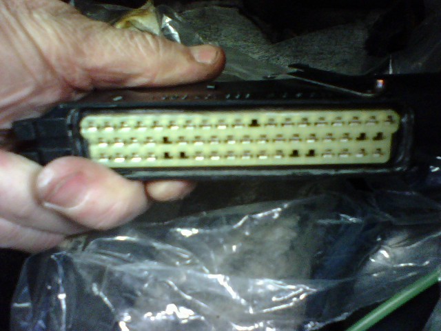
Pic of ECU Connector:

3B Wiring Pinout:
http://www.s2central.net/motronic_pinout_3B.html
3B Wiring Schematic:

Audi 3B Information:
http://www.s2central.net/motronic_02.html
http://www.sjmautotechnik.com/trouble_shooting/20vboost.html
For 3B, specify choice for the extra flying loom cable - often SSC6 connector
Kevin said SSC6 not needed, he will supply connector. So we can use more than 6 wires. Suggestion:
- 5 IGBT outputs
- 2 analog inputs
MembersPage/TeppoKalske page bottom has the standards for SSC6 female pinout:
- either "3B ECU extra connector pins"
- or "AAN ECU extra connector pins"
Or "your custom pinout you like, eg. 4 outputs and 1 analog input" and 1 GND.
As you see, the "AAN ECU extra connector pins" has 3 analog inputs, we use one brake-light switch mounted under clutch (and a series switch that can disable it) to pull down (activate) the (shared) input for shiftcut and launch.
When activated with TPS < iac_tps_threshold launch is activated (TPS can be pressed after activation). Otherwise shiftcut is activated.
In any case, one must specify his extra-connector pinout preference for a 3B engine.
OLD SETUP USED FOR REFERENCE - DO NOT USE
IGNITION out and analog inputs
Motronic55, Pin 1 is Stepper D, EC18 Pin 11
Flying Lead (No connector, I will supply)
- black Stepper A, EC18 Pin 4 (EC10/1)
- green Stepper B, EC18 Pin 10 (EC10/2)
- orange Stepper C, EC18 Pin 5 (EC10/3)
- thick lightblue EC36 Pin 11 (Logic level) (EC10/10)
- vivid-blue mcp3208ch7 analog input with 2k7 pullup (EC10/7)
- transparent mcp3208ch6 analog input with 2k7 pullup (EC10/6)
- pale-blue mcp3208ch5 analog input (EC10/5)
analog input usage: Launch Control / WOT Shift Cut
Flying Lead (No connector, I will supply)
- Analog Input for: "Brake-light switch mounted under clutch (and a series switch that can disable it) to pull down (activate) the (shared) input for Shift Cut and Launch.
- When activated with TPS < iac_tps_threshold launch is activated (TPS can be pressed after activation). Otherwise Shift Cut is activated."
Possible extra feature:
- Air Conditioning / Radiator Fan "Idle-Up" Input