The BigMotronicPnP BMW M52 engine (originally Siemens DME MS41.0)
Currently the supported method involves: HALL replacement camshaft sensor: BMW 12 14 1 438 081 - Hall Effect Falling Edge. Pinout (from 1993 BMW .. .pdf document page#106 (m50 vanos)
The M52 (frequency output) factory camshaft sensor MUST be replaced with a normal digital output / open collector / open drain (that pulls to GND as 99.5% of CAM-sensors used in engines)
In the mean time I´ll be supplying VEMS PDF wiring info.
88pin motronic wiring information
http://www.vems.hu/files/M50Turbo/VEMS_Non_Vanos_M50_ETM_Guide.pdf
Here is crank and cam captures for BMW M52 engine single vanos.
Can this cam sensor be made to work?
The ignition signal is number 1 cylinder.
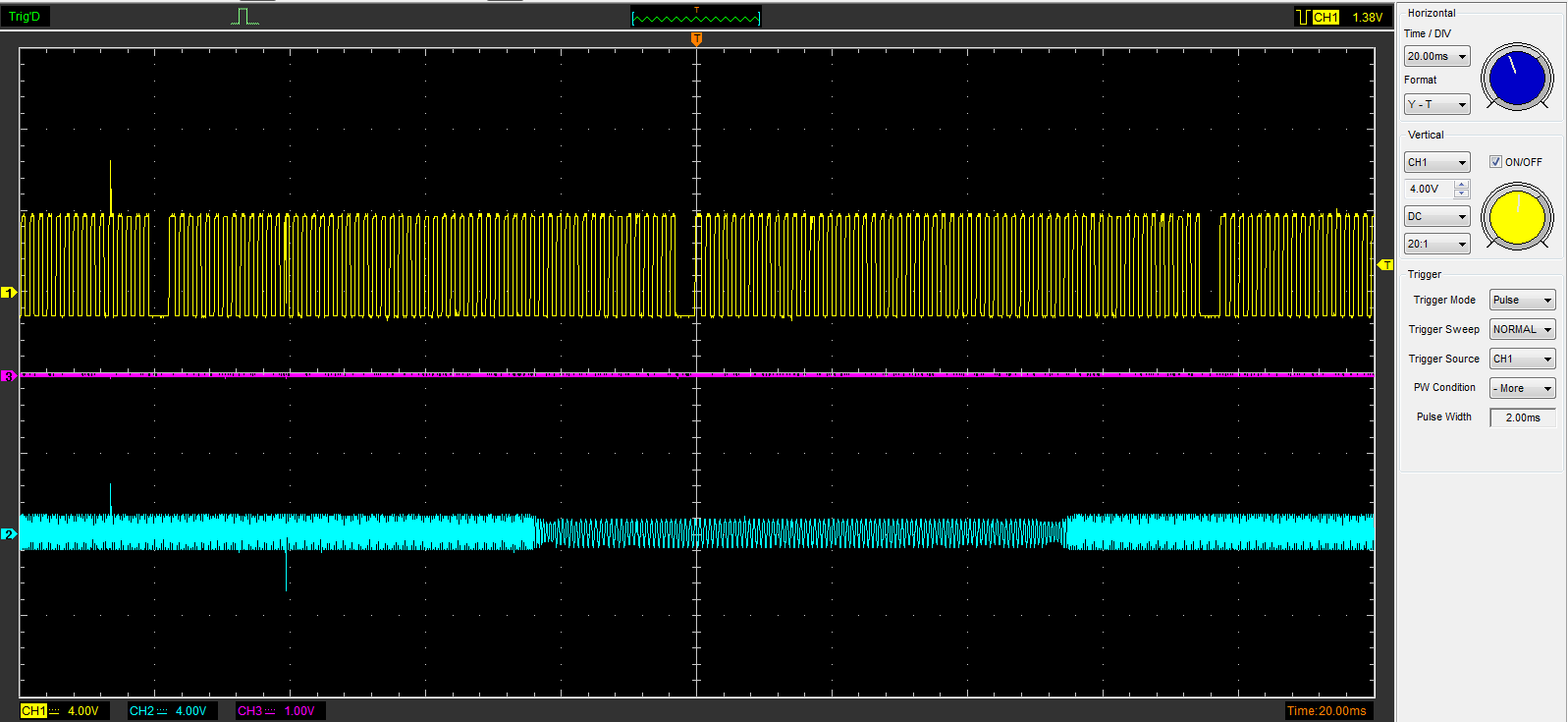
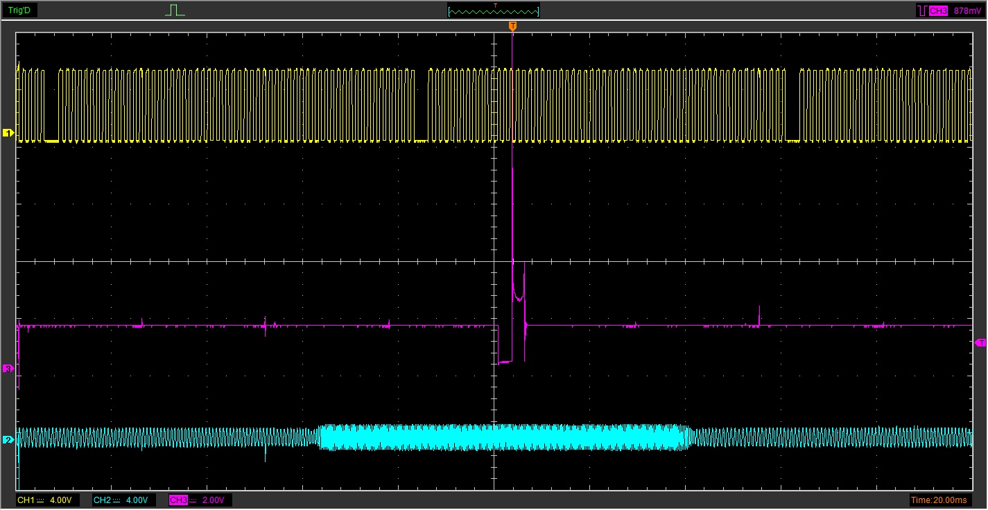
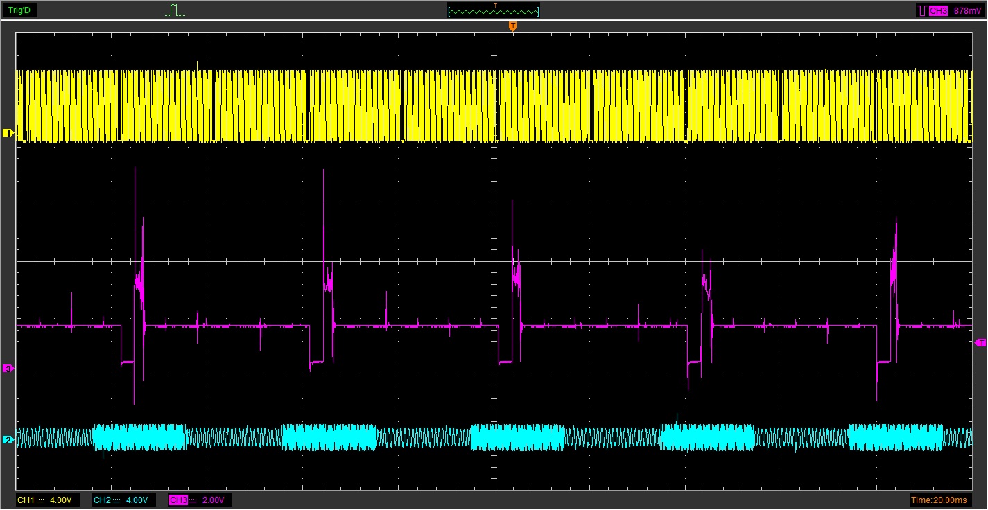
Frequency changes during the toothed section and then go back to lower frequency when the tooth has passed
- even if it's implemented in firmware (fw modification + related config), some signal conditioning (LM1815 or similar) is needed, so Marcell made some prototype (actually with 3 different methods, 1 dropped and 2 good: both with their advantages) to convert signal to HALL type. (for original M52 sensor => v3, or possibly other ECU like Motec).
- assumed 1400 Hz and 2500 Hz signals (but also tested with 1700 Hz and 2100 Hz to be sure)... What are the actual signal freq ? Also, how does it look at the transition ? (sometimes glitch, or changes freq at zero crossing ?)
- This info would be nice for testing (the more realistic the better: for v3 trigger testing we play trigger waves captured from real engine, from recorded triggerlog, and also generated signal).
- Because no scopeshot received, and swapping the cam-HALL sensor is the preferred choice anyway, the freq => HALL circuit has NOT been deployed
Currently the supported method (also see MembersPage/JasonVoytilla/BMW/Sensors
) : HALL replacement sensor: BMW 12 14 1 438 081 - Hall Effect Falling Edge. Pinout (from 1993 BMW .. .pdf document page#106 (m50 vanos)
- 1) power
- 2) signal
- 3) ground
Note: m52 page#98 has camshaft sensor middle (pin#2) going to mot88/pin64
That matches Gunnar's xls for camshaft (just forgot to mention HALL). So
- EC36/13 camHALL input= BMW88/pin64 (middle pin on the replacement HALL sensor connector)
- EC36/26 GND BMW88/pin43
- BMW88/pin65 HALL sensor + supply
- originally 12V was mentioned, but actually depends on the replacement cam-HALL sensor. 5V might be a better choice depending on the sensor.
Unrelated:
- BMW88/pin54 +12V from DME relay (powered by the main relay, actuated by BMW88/73=EC36/16)
- this is not related to cam-HALL (unfortunately was originally somehow listed in a way that caused confusion)
M52 PnP main relay prelling (buzzing ?) issues
Seen on two ECUs now.
ECU Serial numbers are 17304 and 14951.
This has not happened on the other M52 PnP ECUs I´ve bought before.
In November we tested 2 M52 PnP ECUs (random), supplying +12V through the main relay in all possible combinations (ECU powered up, not powered up, ...), and could not reproduce the buzzing.
We purchased 2 M52 full harnesses to be able to reproduce in the lab (+ have a tester, with generic motronic88 female, that can test all outputs, but NOT full "Siemens DME MS41.0" harness)
Can you measure an misbehaving ECU with DVM diode mode; Between main relay output pin (red probe) and testing other outputs (black probe)
- ECU supply pin
- flyback pin
side experience, it happens if main relay which provide 12v feed for injectors and flyback pin is driven from p259 channel. valdas.
TODO: move this to separate page. Essential requirement for tech support that different projects must have separate dedicated pages, not mixed
M42 PNP Ordered
(order-ID 17240)
Requirement to make this E36 DISA Valve compatible.
I?ve had to email the pdf over as the file area doesn?t want to upload the file no matter the file name.
The DISA valve is pin 88-18 low side driven, please modify the ECU internally so that this pin is activated by a spare IGBT or spare INJ MOSFET.
- Mot88/pin18= EC10/9 (ext.output6) DISA valve
The https://shop.vems.hu/catalog/product_info.php?products_id=187 refers to https://vems.hu/download/v3/Motronic88/M50-vanos-vs-s50b32.xls where the M50-nonvanos E column lists the IGBT-s for the ignition outputs (NOTE: make sure to see JPT88 pins, not the xls line numbers!)
- JPT88 pin 25-23-24 (for ign cyl 1,2,3 on 6 cyl M50-nonvanos)
- and JPT88 pin 50-52-51. (for ign cyl 4,5,6 on 6 cyl M50-nonvanos)
On v3/13808 (and 13041) the following ignoutputs are Logic-level (no IGBT - very easy to test with DVM DC voltage measurement with VemsTune if coils are disconnected, save config; outputs temporarily removed from ignouts and set as misc output which can be inverted by 1 click; if set as ignout => testing only makes a short pulse, so possible with LED+protection or special measurement tools, but if removed from ignout and set as MISC output than output stays indefinite time so he can measure as long as he likes, just make sure to upload original config or configure back manually and verify before connecting coils to prevent burning coils):
- JPT88/pin25 (ignch0 logiclevel)
- JPT88/pin52 (ignch6 logiclevel)
- JPT88/pin24 (ignch2 logiclevel)
- JPT88/pin51 (ignch1 logiclevel)
- Not connected (EC36/pin11 no IGBT, not logiclevel, not connected, internally free for any custom usage if needed)
His config shows which IGBTs are driven for each ignition coil. It is discouraged to do any soldering unless he can clearly verify according to the .xls and the config.