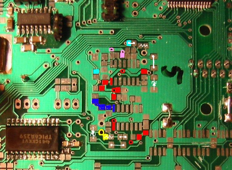
I'm trying to connect HALL to both primary and secondary inputs on my development board.
This is what I've figured out:

The red areas are +5V, probably good to use as pullups.
The magenta area is not trigger 1. It's +5V. Trigger 1 is the 'upper' larger hole in the same area.
It should connect to the cyan area, which is the input pin on the atmega.
Trigger 2 is the Yellow area; it should connect to the Blue area.
Does anyone have a good idea on how to make all these connected?
- DO NOT connect HALL to IC1 and IC3 traces
- Use the input pins and add the pullup to the input pins
- apply pullup
- Recommended to apply some (diode) protection, eg. 5.1V zener (SOD80 D14 and D27) so IC1 and IC3 get clamped. On a production circuit this is a must.
- trigg2= R91 stuffed, D24 should be a short, and D27 a 5.1V, zeener SJ5 shorted
- trigg1=R55 stuffed, D13 short, D14=5.1V zeener, SJ2 solderd
