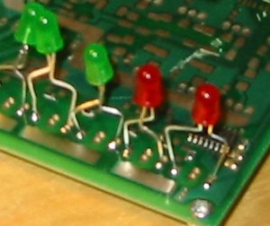
Trigger output
For testing the trigger output I've soldered a 1k resistor from the output at the IGN_259 and a LED over the output to GND.

HALL: (done)
Trigger1:
Pin is connected to IC by 10k R55 and shorted SJ2.
It's protected by a 5.1V zener on D14 and a short on D13.
Trigger2:
Pin is connected to IC by 10k R91 and shorted SJ5.
It's protected by a 5.1V zener on D27 and short on D24.
The signal should look like this 'hall signal -> pulled up by 10k to 5v -> 10k series resistor -> 5v1 zener to ground -> ic1 pin'. Thanks, Dave.
Schematic diagram showing the recommended hall setup