Audi-AAN/ADU/ABY installs are usually quite easy and smooth nowadays. Rarely (these are almost always home-modified setups) there are some issues. This is one of those cases.
New Info. Sorry guys i made a silly mistake with my scope. Basicly my pictures of the cam sensor are wrong and are inverted in my pictures! Please look at http://www.s2forum.com/forum/attachment.php?attachmentid=27419&d=1277585384
I'm sure you need to register to see these pictures. (if one has cookies already set in the browser that might cause confusion).
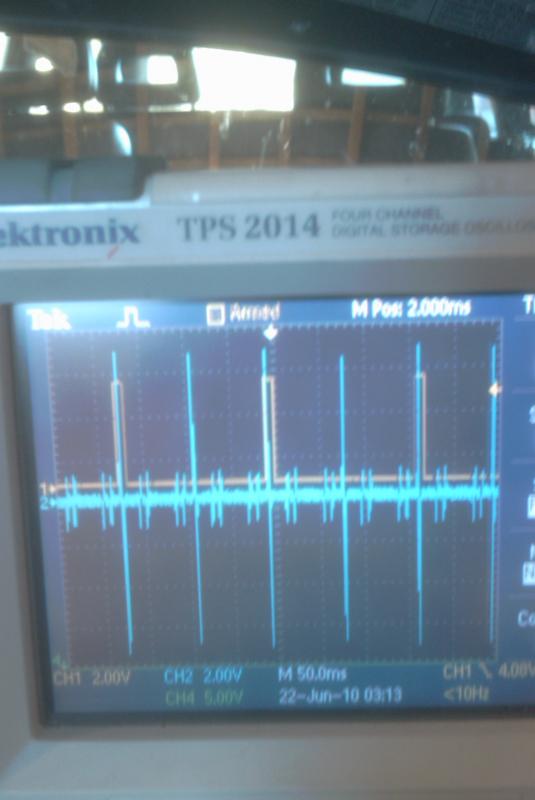
Right, i had the scope input on the cam sensor connected incorrectly in my first pictures. Instead of ground i was connected to vcc 5 volt, hence the output looking like it was inverted. Here is the new picture. Both the crank pin and cam are on the same scale eg 1 volt/div.
- the cam output drops from about 4.8v to 0.3v.
- that is perfect. The atmega128 (there is clamping for higher voltage, but processor sees almost same voltage in this range as the input) specifies certainly low and high for these voltages. (below 0.7V and higher than 3V are good)
- The crank pin is AC and is about 6 volt peak to peak. As RPM rises this voltage increases slightly.
- the amplitude should not be a big problem. See GenBoard/VerThree/Schematic The LM1815 circuit is designed to work in a wide range of amplitude. Too low signal amplitude would be a problem when cranking in very cold winter mornings.
- however, in problematic cases a very weak DC bias could help. I assume you have appr 1k VR sensor x 1k pulldown resistor = 500 Ohm effective pulldown to GND.
- 42k (or slightly stronger, eg 27k) pulldown to -8V would be appr -8000*500/42500=-94mV DC bias, that could get the signal away from the 0V (at 0V it is easier for noise to get injected). Pullup to +5V can be tried, but not as effective as toward negative, as it somewhat defeats the "LM1815 minimum arming voltage threshold".
The voltage messured on a stock aby is 30 volt! Mine is only 6. It is true that with 30V signal the signal to noise ratio is better. But it is not the 6 volt itself that is a showstopper, but the relatively large noise compared to the signal.
- either the signal can be made higher or the noise suppression can be tuned with DC pulldown to negative -90 .. -300mV or pullup to positive +90..+200mV
- accurately measure the crank pin to sensor distance. This distance should influence the output from the sensor. I will put blu-tac on the sensor and spin the crank and measure whats left.
I get this trigger fault whenever cold and also at 2200 rpm almost exactly. My wife is calling the car "the frog" as it bounces violently during this trigger fault. Its actually shook something loose on the exhaust as it rattles on the ass of the car now.
The new InputTrigger/UltimateMeasurement secondary trigger log (which needs upgrade to experimental/1.1.76 or 1.1.78 firmware, and new VemsTune) captured during frogging would show if the offending crankhome-VR pulse is before or after the correct pulse. Than we could make some filtering attempt in 1.1.79 to filter it in software (it's not easy, because even if the offending pulse is later, it might be sensed first during initial sync in some cases).
Sorry for all this confusion guys! Thanks for your help so far. !!
Inverted measurement, false conclusion:
- apparently there are 2 types of HALL sensors, even from the factory
- "mostly 5V" that we've seen so far
- and "mostly 0V" as on this engine. This in itself does not cause a problem if other parts are stock.
- a significant modification in this case is the 7A flywheel.
- AudiTrigger/CamHALLInverter was made to filter out the noises of the 7A flywheel. But that assumes the HALL signal is mostly 5V as the on the image on InputTrigger/AudiTrigger with the German text shows - and also as we've seen on many-many audis before
- without a normal flywheel one would never notice. But with the 7A flywheel this gets important.
- There were many trigger errors originally. After changing the 2 VR sensors the engine runs much better now, but there are still a few trigger errors.
- Even though changing signal thresholds (by switching to other VEMS box, or moving or replacing the sensor) might apparently help a little,
- the good solution is to change the HALL sensor to a "mostly 5V" type, or get rid of the internal cam-HALL inverter that is not appropriate for this HALL-sensor.
Motronic is apparently less sensitive on VR-HALL relative position.
- With VEMS, the VR must be in the HALL window. That is a hard requirement. We cannot make a software workaround for that.
- For the offending 7A pulses (that are best filtered out with the correct choice of cam-HALL-inverter or no-cam-HALL-inverter) software filtering is theoretically possible. We are investigating that possibility so future cases can benefit.
Scopeshot of crankhome-VR and HALL:

- Scope pictures are all taken at the sensor plugs.
- [s2forum] page shows the crank pulse is almost perfectly in the middle of the cam sensor window when i zoomed in with the scope
- you probably have to log in. but I believe you. Now that we have the overall picture most of the speculation there is outdated.
In any case,
- this HALL signal is mostly 0V. That means it would be more noise tolerant without the cam-HALL inverter
- and 360 degrees offset in config, configured "without cam-HALL inverter" if it is now configured "with cam-HALL inverter").
- It would have been great to see this scopeshot before sending out the new, motronic55 ECU to help investigation. Than we would have had set that up without the internal cam-HALL inverter HW !
The cam sensor is stock AAN unit. I tried replaceing it with ABY but there was NO difference to performance.
The HALL sensor is at front of heat at cam pully. (Stock audi AAN). The 1-window wheel is mostly metal with small gap (stock AAN)
The VR noise signal (4 evenly spaced noise)
- 7A flywheel i have has holes near where the pin is. Not inline but on the back. I will post picture of this flywheel before i welded on the larger pin on s2forum thread
- the noise is very likely because of the notches of the 7A flywheel (to clear the tool). These would be filtered out completely if we'd seen earlier that this HALL is different from the usual, mostly 0V and hadn't applied the cam-HALL inverter.
Can i remove this inverter ? I have some electronic skills and am willing to try if showen with a picture what to do. Thanks des
Yes.. Removing the inverter is extremely simple, ~10 minutes.
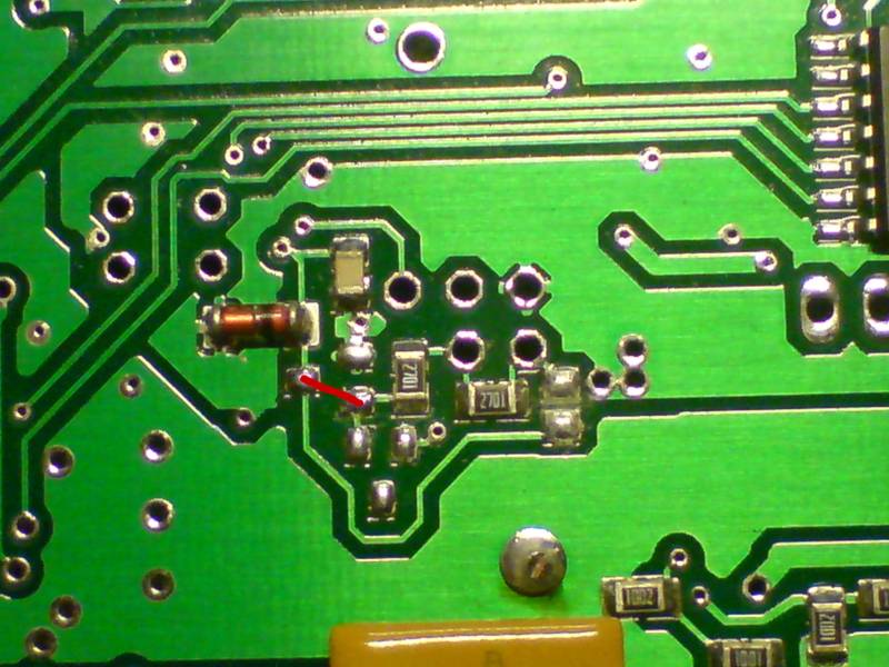
Image shows how the components should look without the cam-HALL inverter:

Image is from GenBoard/Manual/InputTriggerHardWare
- a small SOT23 PNP resistor (BC817 or other) at the bottom of the board, around the middle must be removed, and replaced with 0 Ohm (B=>C pads effected)
- the NPN's collector pullup resistor must be removed as well !
- It is a vertical SMD 0805 to the right from the NPN (by appr image_width*0.25). Follow the meandaring trace. It's not mounted on the picture.
- the "base" or protecting resistor right next to the NPN (~2k7 marked 2701 on the picture, 272 would be same) can stay (need not be replaced by 0 Ohm)
Disassembling+assembling the Motronic-55 device requires a bit skill or patience, appr. 20+20 minutes
- disassembling+assembling the Econoseal-36+18 box is much easier. It would be better to do that (or do that first). The cam-HALL inverter (and the whole circuit) is same.
Thank you for the cooperation !
If you link your vemscfg actually used accessible from here (so one does not need to register), I can help changing ignout sequence with 2-3 positions and trigger tooth by 9 so the final effect is 2.5*144=360 degrees.
- Should my timing be 58 or 53 teeth for TDC?
- "TDC after the trigger" = 58 degrees is closer to realistic