Dear Vems,
You provided pictures and great explanations to add 2 analog inputs thanks for that.
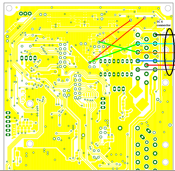
But I saw that I already have 2 existing green wires on my 3B board that share one extremity of your 2 red drawn on the board.

What shall I do with these wires? I also have light green and orange wires at the position of your proposal for a analog ch2 and ch5.
I have added in colours on your picture the existing wires (black, light blue, blue, grey, orange, red)

that are going from the board to the existing sc6 connector.

Maybe I do not have to do any modification on the board ? Are the existing wires (black, light blue, blue, grey, orange, red)
input already available from factory ? output ? pull up ?, protected ? which channel ?
- Can you check the paper that came with your ECU ? That is the best source, as your device might be different from default if ordered with special specs
- especially for 3B with SSC6 which has different best set of pins depending on circumstances
- especially that this very controller was modified later, AFAIK
- if the paper was lost, you can also test easily. Take a 1kOhm resistor and pull the pin in question (from SSC6) to GND, than to +3..5V. Watch the "analog inputs raw" gauge-group during this.
- that is safe to any pin of the extra connector SSC6 (or econoseal10 in newer devices) even if it's not analog input. Just do not apply more than 5V ( >5V would be damaging even through a resistor)
Getting extra analogs
Do these to get 2 pcs. of 0-5V analog inputs.
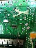
- solder 2 wires to the bottom of the board like on this image:
-
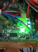
- Remove the two resistor marked cyan and solder two 10kOhm resistor marked black on this image:
- The two resistors are the pullup resistors to the two analog input, so if remove them, the analog inputs are become only protected.
- wire EC18 pin 2 and pin 3, this way you can use analog in ch2 and ch5