Runout
Some factors can impact VR trigger quality.
triggerwheel is not centered on the shaft
Sine wave will modulate the VR signal amplitude, so the arming threshold becomes important.
or the amplitude of tooth pulses is not equal
This is a common error with homemade trigger wheels that have same depth of missing tooth as normal teeth (this results in a higher amplitude around the missing tooth). Professional wheels have less depth at the missing tooth. Examine a 60-2 Bosch wheel.
If in doubt, record VR signal with scope or your notebook soundcard.
Variation in individual tooth-height just makes the problem worse. Mik was the first to experience such problem when he patched his original (quite exotic) 18-1 + 18-1 crankwheel with a surgery for normal 36-1 tooth. The added tooth had smaller amplitude than the original teeth.
Soundcard can be used to record VR signal
WhatEverYouDoYouDoItAtYourOwnRisk !!! (take care of your soundcard)
- voltage divider with 10..22k and 1k resistors
- series cap > 100nF (220nF is perfect. Most soundcards have internal cap, but it doesn't hurt to have one just to be safe)
Since the VR signal amplitude can be quite high (especially at high-RPM, often >30V), the line-in input should be preferred to the mic-input. With mic-level input a much higher divider can be used, eg. 100k and 1k.
- Some playing with the mixer is always needed to get a wav with desired amplitude
- at idle the signal must stay below 10% amplitude so it stays within limits at high-RPM.
LM1815 arms at about 0.8 * peak
Note that the 20% safety margin in the VR chip isn't shown. The margin should eliminate any runout problems on a multitooth triggerwheel, but if the teeth for some reason result in a 20% amplitude difference there will be trigger problems.
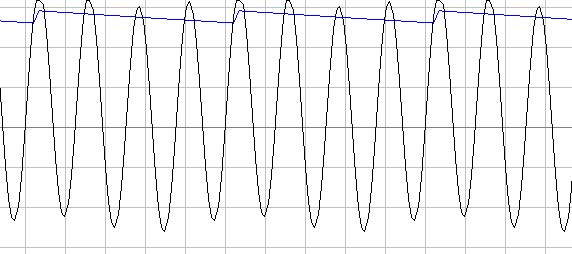
This is a simulation of a four tooth triggerwheel at 3k (V8). The trigger occur when the VR signal fall down past 0v. The trigger is armed for the next trigg after going higher then the blue trace.

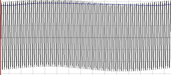
60 tooth at 3000rpm

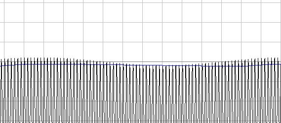
The same triggerwheel, with the same runout at 6000rpm. As you can see the margin between the ARM threshold and the VR signal has decreased.

Notes
- the pictures do not show modulation correctly, they are using addition instead of multiplication in function VR(t) = sin(t / t0) * (1 + 0.2 * sin(t/(36*t0))). Since only the peak is important, and the negative peak is not, this changes nothing
- I couldn't easily simulate the missing teeth but that doesn't change anything
- LM1815 datasheet says typical arming treshold is 80% of peak value, but worst case is 90%. (deviance to the other direction, 40% does not cause problem). Should we measure this characteristics of each LM1815 during board testing ?
If someone want to waste some time on simulating this better:
http://www.vems.hu/files/JorgenKarlsson/triggersim.zip
Proposed solution
- appr. 150k resistor in series with C38(=220nF). This is an onboard modification. 220k sounds a bit high, but it would work. Please do this mod for v3.0 .. v3.2 boards you assemble to full units for your customers. Easy to do cleanly with 3 steps (unsolder C38, tiny tracecut, some scratch of solderprotect, solder C38 and series 0805 resistor from rescukit). This is the standard factory-populated setup since v3.3 (under manufacturing)
- or jumper LM1815 for non-adaptive mode (eg. pin5 to +5V for max arming threshold).
See also