This page is about Multitooth Trigger Wheel that is often used to trigger GenBoard (especially v3.x).
Actually, best named missing tooth wheel to distinguish from InputTrigger/MultiToothNoneMissing, InputTrigger/ShortGapTrigger and extrapulse (and special rover / elise) trigger setups.
- note: for homemade HALL setups, the extrapulse is a remarkably nice simple option (requires firmware >= 1.1.96), especially if made with bolts (=> less bolts needed).
- Traditionally VR was cheaper (for car manufacturers)
- while HALL is less prone to noise and easier to install (especially by less experienced installers, or without oscilloscope and careful inspection).
- HALL is recommended for any home-made wheel. (with the simpler ECU interface, less demanding wire-shielding and testing, the total cost is better than VR anyway)
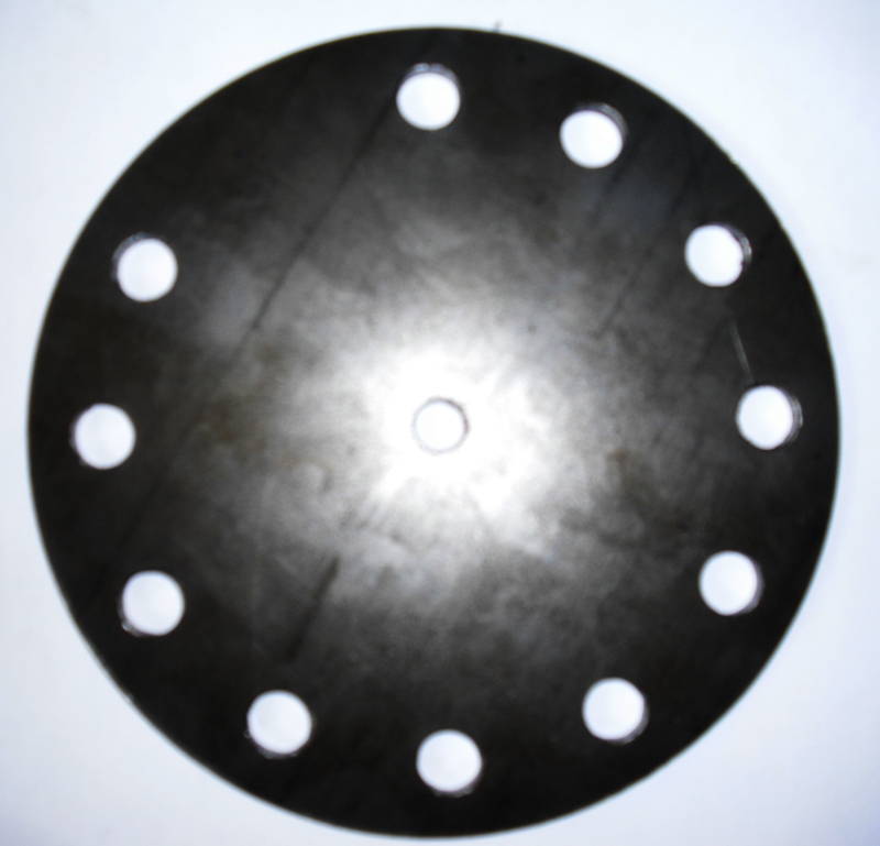
12-2 pattern (missing 10 and 11'oclock drill) crankwheel for 3cyl, 4cyl, evenfire 6cyl, 8 cyl
12-1 wheel: D=12mm drills (D=14mm would be better) into 5mm steel disk (not stainless). Ddrill=130mm, Douter=159mm.
- normally 12-2 recommended instead
- because with a 12-1 crankwheel, during cranking the RPM can change more than 50% between 2 normal teeth (30 crankdeg) especially at TDC with high compression (in that case advanced filtering might be needed with adjusted, eg. 170% threshold)
- This is 12-1 because it is mounted on the gear-driven cam of a I6 (producer-gas powerplant) engine where 12-2 is unsuitable.
- Note that because of the high magnetic flux, 1GT101DC '''HALL sensor (mounted axially) should be rather far away (appr 1.5-2mm) from the wheel
- so the gaps (high voltage) are at least 20% of the period (measured DC voltage is >800mV when rotating)
- lower 5..10% would be no problem for the controller HW or firmware, but axial play would make a bigger angular error
- probably unsuitable for VR sensor (although experienced installers could probably make that work also).
- tooth0 is 12'oclock tooth1 is 1'oclock, tooth10 is 10'oclock (tooth 11 is missing)

Here is an [example 24-2 triggerwheel CAD files] suitable for almost any engine
- cylinder number: 1,2,3,4, evenfire-6, 8
- and also Harley V-2 (which is 2 cyl out of 8) and even 60+150 deg oddfire V6
- but: NOT good for straight-5 cyl, see the 15-1 wheel below for that
- this is NOT for VR sensor, but for HALL sensor, like [Honeywell 1GT101DC] HALL sensor. The gap is slightly bigger (9 deg) than the meet (6 deg) to allow sufficient (>10 mm) tooth spacing !
Jorgen designed a 15-1 and 10-1 wheels for the 1GT101 Honeywell HALL sensor ,he says its the BEST.
I made some modification to the wheel to make it lighter.Please check it,will this affect the performance of the wheel?
The odd number is because its made for the 5cyl Audi engine.
http://www.vems.hu/files/MembersPage/NanassyPeter/TriggerWheels/15_1light1.dwg
- move the teeth 12 degrees clockwise for better dynamic balance. The missing tooth should be in the middle of a spoke (this creates another symmetry axis)
- make the teeth slightly longer, min 6mm thickness and min 10mm length recommnended
V3 supports either HALL or VR sensor (jumper selectable). Multitooth factory wheels used to be mostly VR type, but more and more HALL after 2000.
HALL (audi AAN addon):


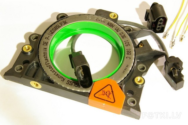
VR also exists (audi AAN addon, HALL recommended for new installs):

- 24-1, 36-1 and 60-2 are common multitooth wheels: these are used successfully
- 135-136 cranktooth requires special HW InputTrigger/AudiTrigger (which is standard VEMS ECU option, and fw support)
It is a good idea to have someone verify the trigger settings. To allow this, make a comment sentence in your config.txt, something like the following:
- as .... (image, link to another page) shows
- TDC of cyl1 (and cyl4) comes
- 83 degrees after the point, when
- the first tooth after the missing tooth just passes the trigger (considering the rotational direction).
- that is 8 tooth and a little on the 36-1 wheel.
- we place trigger_tooth to 20 degrees (02 teeth)
- so 63 degrees remains for ign_tdcdelay
- so the sum is 83 degrees
If these are correct, the n[] table will reflect real ignition advance (not with offset). If there is a big difference (eg. the cylinder number is wrong, or rotational direction), that can be a serious problem.
GenBoard v2 hardware mod: first thing you need to do is to make a small change in the input trigger on the board:
You need to connect the output signal of the opto (inside the board!) to the IC3 pin of the avr(available on jumper J2). INT6 input was used originally, but we changed to use the IC3 pin for the primary trigger, because it has hardware-capture capability (more precision), and reserved INT6 for the CAM signal for dual-trigger applications.
Material
HALL and VR work with magnetic field, which is not disturbed by Al. So steel (not stainless) is the common wheel material.
Sources
If you want to fit a trigger wheel and don't have one fitted from the factory, there are many sources:
- http://www.racerpartswholesale.com/electro2.htm
- http://www.electromotive-inc.com/
- EdisIgnition
- Napa part number CSS304 (tooth wheel), CSS400 (sensor)
- many others