Subpage of InTake/DriveByWireThrottle
Kevin sent the following information:
It is for the VW/Audi cars made from 1996-1999. Drive by Cable.
TODO: image of the actual throttle
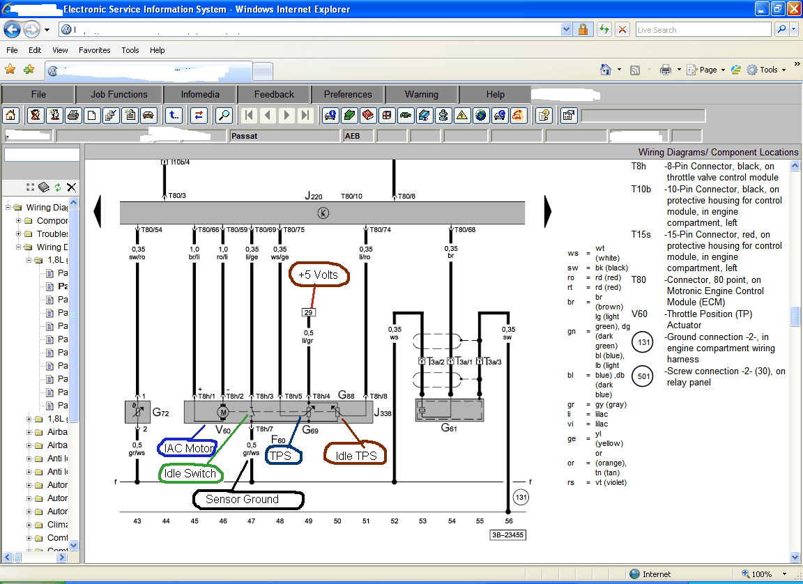
It is a small electric motor and gear that turns a larger gear, that opens the actual throttle plate up to ~15%,
and
- it can also actually close the throttle plate farther than it's resting position as well.
I have tried to use a PWM to control this, but the throttle plate movement is "weak".
For example, I can have it slightly open, and take my finger and physically move the plate, and it will not "self correct".
This translates to the engine speed fluctuates greatly, and proper control is impossible.

yes, because from the schematic it looks like +12V and -12V bidirectional drive is needed on the motor to move one direction or the other
This units operates OK at 100% open, and it will close to the resting position when the DC is 0%. But everything in between is bad.
(And I don't know how to close the plate from it's resting position to lower the idle from base)
Sensors
Finally, there is an "Idle Circuit" that I cannot use, because it is wired (internally) to make the TPS% go to "100%"
when connected.
This means that the TPS% moves when the IAC is active.
- This TPS is also "backwards" - "TPS100% setting" is small, and the "TPS 0% setting" is large.
- This itself is not a problem
Wishlist summation:
- Proper idle control
- Add "idle switch input" in ecu firmware
- is this needed ? Did you try simply calibrating higher value for TPS-LOW than for TPS-high ?
- the throttle-controller code would watch a 2nd analog input for throttle-command (I recommend TCS abbreviation, because throttle-pedal-sensor abbreviation would collide with throttle-position-sensor we already use)
- decision is needed for connections. In any case, for internal idle-threshold the throttle-command (pedal sensor, not the actual throttleplate position sensor) must be used, for safety
- Have everything work without wire swapping, to suit Plug-and-Play installs.
Please measure current, and try to confirm that reverse driving voltage closes it (try to be careful, and use fuses).
Jorgen's comments :
There can be different versions of this throttle, but the ones I have seen worked fine.
- This throttle has worked good before
- Q: (driven how ? simple PWM or with +12V / -12V signals ?)
- but there is a trick to it. As it turn the throttle itself it change the TPS angle, this means that as soon as the idle control is activated the TPS will change and the idle control will be turned off instantly.
There is an idle switch in the throttle, you need to use that to short the TPS signal to ground.
- As this throttles TPS has the wrong polarity you need to connect it with the opposite polarity. This unfortunately make the idle switch short to 5v instead of 0v.
- So You need to use a small signal transistor (same NPN + 2 resistors as in the InputTrigger/WheelSpeed and AudiTrigger/CamHALLInverter ) to reverse the polarity of the signal.
Possible interference with TPS-acceleration enrichment
There will be a sudden jump in TPS voltage when the idle switch become inactive as the TPS signal go from 0v to the output of the TPS instantly. I have expected this to give a squirt of fuel through the acc enrich but I have not tuned any of these cars myself and the customers who did the tuning didn't notice a problem even if I asked them to look for the problem. I'm sure that we can come up with a workaround if it's needed.
But it would obviously be best if we could have an idle signal input on the ECU.
- What would be the exact semantics ?
- If idle-signal input==active (normally active below 1.6V, or above 1.6V if inverted input is chosen) than we consider idle-mode (pretend that TPS < iac_tps_threshold) regardless of TPS voltage ?
Plan - steps
We need to find out
- hardware requirements, like current consumption in both direction (when moving, and likely higher when stopped)
- if the +-12V drive assumption is correct
- voltage mapping of the analog feedback signals for min 8 points, and min 4 points around idle
- implement firmware code for it
- find/tune suitable PID parameters
- write some vemstune help text for the new dialog
I'm pretty certain that Jorgen Karlsson is more knowledgable than me, and he might confirm or deny some of our assumptions.