This page documents several types of coil over plug items.
Subaru
I've got some COPs for a Subaru. Here is an [hi-rez image]
Part number: 22433AA330
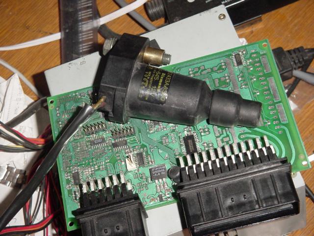
Diamond (denso logo; made in Japan) F-645 12V
Use with transistor ignition
9002530 (this is a build or serial number as they are all different)
There are 2 wires on the unit. Yellow and red. Resistance is 0.9 ohms - in both directions (?).
There is infinite resistance between the ground screw and either of the 2 leads. Very likely, this must be a dumb coil.
Can you measure inductance? Apply 0.8 .. 1msec dwell (first, only increase dwell if results justify) (with some sparkgap there) and measure current rampup with scope or DVM (check DummyIgnition):
- Apply a 0.1 Ohm series R (or a calibrated wire) to measure current rampup with scope
- apply a known constant freq and known constant dwell and measure supply consumption with DVM: the max current (and therefore L) can be calculated.
Subaru
Part number: 22433AA421
Diamond FK0140 is used on many Subaru models:

Dwell is said to be 3 ms according to [Link Electrosystems], along with a suppression capacitor. It is a 3-pin design with internal ignitor:
- Coil positive on Pin 1 (with the raised edge)
- Ignitor ground on Pin 2 (in the middle)
- Ignitor positive on Pin 3 (at the clip end)
- Coil ground on mounting bolt.
COIL ON PLUG FK0140 Features:
- Integrated coil driver circuit with diagnostics
- Fast primary and secondary rise times allow for multiple strike capabilities
- Very high weight – energy ratio for maximum performance efficiency
- Design provides reduced RFI
- Precise electronic timing
- Over 150,000 mile durability
- Robust electrical connection to the spark plug
- Reduced under hood complexity and enhanced engine appearance
- Waterproof primary connector
- Coated laminations for corrosion resistance
- Greater packaging flexibility with reduced assembly costs
- Energy adaptable for high demand combustion requirements
- Tooling required
Specs:
| Output Voltage | Spark Energy | |||||
| Primary Break Current | Output Voltage | Secondary | Spark Energy @ Vz = 1,000 Volts | |||
| 25pF Load | 25p-1M Load | Rise Time* | Current | Duration | Energy | |
| 6A | 28 KV | 19 KV | 11.2 usec | 53 mA | 1.0 ms | 22 mJ |
| 8A | 33 KV | 23 KV | 10.2 usec | 67 mA | 1.1 ms | 28 mJ |
| Open Circuit Voltage: 39 KV @ 6 break Amps 44 KV @ 8 break Amps | ||||||

How best to drive this one?
VAG

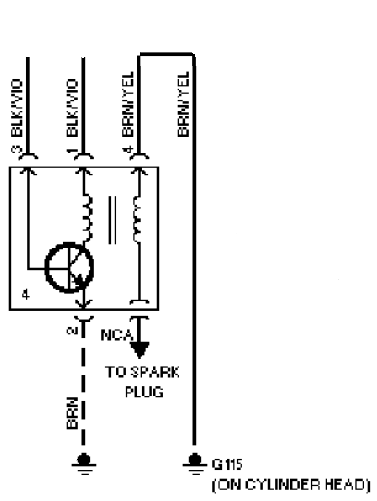
The above is active coil, since it has the switching internally.
1J0 973 724 is the 4-pin plug for the VW coil
4D0 906 232 is the 3-pin plug for the VW coil
For passive coils (ment for inductive apps), you can measure appr 0.4 .. 1 Ohm on the primary winding (at least in one polarity, but usually both)
I heard some of these part numbers might be the connector, not the transformer. Double check.
The coil in the 1.8T 20V (1998-2001) is called 058 905 105 (3-pin?).
I think Dave, Jorgen and Sly collected info about many (mainly VAG) TODO: find it in the wiki and move or link. I'm afraid they dumped it (zzz) to some MembersPage (or even irc).
A [A4 schematic] that uses these kind of transformers.
VAG TFSI coil
Has anyone successfully used these coils?
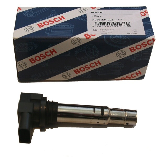
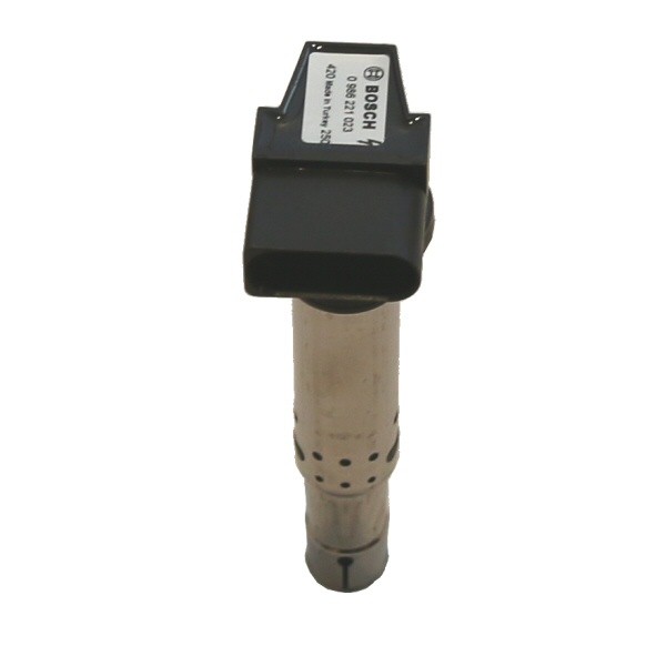
- Bosch "0 986 221 023"
- VAG 036905715F
- Commonly used on VAG (VW/Audi) TFSI engines (year 2000-2010?).
The pinout is as follows :
- Pin 1: ECU Ground
- Pin 2: Engine block Ground
- Pin 3: 12 volts + (switched)
- Pin 4: Signal from ECU
Note :
- I've connected pin 1 and 2 to the cylinder head.
- The resistance between ground and the signal pin is 370 Ohms.
- not sure how you measure, but maybe it's actually voltage, like an "internal diode clamp" ... eg. you can measure with DVM diode mode (often 400..600mV measured; possibly different in the 2 directions)
- The signal is attached to stepper output. I can't get any spark.
- is it possible that the given stepper output is damaged ? Often 270 Ohm limiting series resistor is used when stepper is not used for stepper motor/relay/idle air solenoid, but used only for active coil (to protect stepper chip against accidental shorting to GND or +12V)
- test with DVM ; or a resistor (270 Ohm .. 1 kOhm) and LED that the output works (VemsTune / outputs / Test mode=ON). Needless to say: disconnect the COP while doing this test. The resistor+LED is better than DVM, because even a 2..3 msec pulse can be seen.
- The pinout is different from the VAG 115 coils, still same connector - beware!
Coming next :
- I will measure voltage at the signal pin
- Stepper output is what I've used so far
- Maybe logic level +5V output with 250 Ohm limiting resistor will work better?
- don't know, but shouldn't hurt to try
- however, before trying, doublecheck: measure in the COP connector that both grounds are connected (to each other; and to engine/alternator ground)
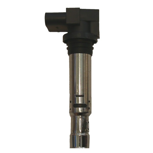
Does anyone have pin out and charge time information? For VAG coils 0 221 604 109 / 06H 905 115
See also
- back to IgnitionPage
- DummyIgnition