Procedure to calibrate or recalibrate your WBO2 controller built-in to VEMS V3
See GenBoard/Manual/WideBandDualWboHardware for 2nd channel wideband controller if needed (irrelevant for 1st channel).
These are normally done during v3 assembly. It can be useful for debugging if something is wrong. Check WBO2 + supply and other wiring (the most common mistakes).
wbo2_pump_pw_zero and wbo2_nernst_dc_target board calibration values are the results from these adjustments
Note: the following information is required for any WBO2 related question: wbo2 values (pump zero dutycycle, nernst dc target), controller serialnumber (preferrably also orderid), sensor resistance (Ohm measured between pin2 and pin6), acquired wbo2 calibration value.
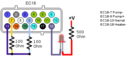
- Connect pump(-) and nernst with 100 Ohm
- connect nernst and pump(+) with 100Ohm too.
- Connect a LED's cathode to Heater(-).
- Anode with series 500 Ohm to 12V

Verify Pump-
- First Measure the voltage between the GND and Pump(-). It should be appr +4V (3.85 - 4.15V)
Measure Pump+ and Adjust Pump-pw-zero
- Measure the voltage between pump(-) and pump(+)
- DVM's COM (black) = Pump(-)
- it should between -4mv and +4mV, when wbo2 is off. If the voltage not in the specified range, adjust pump_pw_zero variable
Verify Heater
- turn on the wbo2 (mde02 in the terminal, or WBO2 calibration wizard in VemsTune)
- The LED should start lighting.
Nernst-DC target
- Connect DVM's (+) to nernst
- note: DVM reference (-) is still on pump(-)
- after a while, the voltage should rise to +450mV. Adjust wbo2_nernst_dc_target variable to get close.
- optional step: Switch to the display's 7th page (Terminal: mlp07). Check Ri(Top left corner), it should between 90 and E0.
Quick Reference
| DVM - | DVM + | Expected Val. | Var to Change | Notes |
| GND | pump- | +4V (3.85-4.15V) | Just verify | |
| pump- | pump+ | -4mV to +4mV | pump_pw_zero | WBO2 off |
| pump- | nernst | +450mV | wbo2_nernst_dc_target | WBO2 on |
- WBO2 Basic calibration settings in Vemstune Basic settings -> ECU calibrations