We need to add detailed description of sensors and configuration parameters here. Most can be had from GenBoard/InitialConfig page.
GenBoard/VerThree knockdetection HW
Needed for Knock Sensor input:
- R1, R2 Knock Channel 1 (10..22k) (analog signal amplitude gain can be adjusted with these; but also in the digital domain - in config)
- R3, R4 Knock Channel 2 (same as R1,R2)
- R17 1M
- C1 Knock Channel 1 (100nF)
- C2 Knock Channel 2 (same as C1)
- C14 0.22uF
- C16 100nF
- C18, C19 22pF
- Y2 4MHz XTAL (16MHz might work with matching config)
- U5 TPIC8101DW (not in rescue kit! Optional, see WebShop)
C17 is no longer used. (was: 2.2nF, can now be left off)
V3.2: if you ordered knock-kit (in same order as genboard) than U5=TPIC8101DW and Y2=crystal already soldered onboard (crystal missing on a few boards sent out before 20041030.)
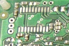
The knock sensor chip installation:
Pin 1 points to the connectors-side. (so pin 1 points to the short side of the board)

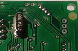
The crystal goes next to the chip.

v3.3
The knockchip and 4MHz crystal is installed (if ordered v3.3 with knock-kit), the only thing needed is to connect the sensor input through the 3 pin header (pads) at the northwest corner (looking at the "top") :
- North pad (close to board-edge): knockA signal (channel 0) (usually through EC18pin3)
- Middle pad: knock GND (usually through EC18pin2)
- Southern pad: knockB signal (channel 1) - usually not used
TODO: take pictures of board region around knock chip
If the knock signal is not routed via EC18, it can be routed through a connector or flying loom cable mounted through frontplate or endplate.
See also