[[Manual: Detailed.Central.Keyboard.Install]]
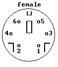
Viewing the female connector (on the computer), the pinout is:

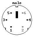
Viewing the male connector (on the keyboard or mouse cable), the pinout is:

Pins are normally used as follows:
- pin function
- 1 data
- 2 (reserved)
- 3 gnd
- 4 +5v
- 5 clock
- 6 (reserved)
- JP header near AVR (pin1 is near boardedge)
- pin1 VCC
- pin2 GND
- pin3 DATA
- pin4 CLK
TODO:
- add these to the manual
- must revert the manual SVN from the backup (because it's not loaded on the new server, apparently)
See also
- GenBoard/BuildProcedures/LCDconnect (pinout at the bottom)
- GenBoard/Manual
- [Atmel's keyboard related app note AVR313]