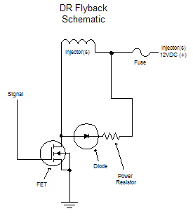
The old recommendation was DR flyback

A Diode and a small series power-Resistor returning to VBatt for every channel, this is the DR flyback. The voltage on the injector has exponential decay. Here is an example with R=22Ohm: The peak voltage the FET sees is
Umax = VBatt + Ud + 22 Ohm * Imax = 14V + 0.7V + 22 Ohm * 1A = appr. 37V, maybe max 40V with some margin and a slightly hesitating diode (FET is OK for max. UDSmax = 60V )
Below is a picture of a scope capture from MembersPage/DaveBrul's DR setup.

The above fast decay is perfect for final closing, but not ideal for lowZ PWMing. Note that although the above formula has 22Ohm, if you are calculating the tau time constant for the exponential formula exp(-tau * L/Reff) (eg to fit on the scope-picture) you will find that Reff = Rfly + Rinj = 22 Ohm + 13 Ohm =35 Ohm which is because you have to calculate the injector's internal resistance (13 Ohm for a highZ in the example) into the formula, since that also dissipates power. So a DR flyback with 22 Ohm is only about (22+13)/13=2.7 times faster than a DR flyback with R=0 Ohm.
DR flyback works well if one does not exceed the limits (of the FET UDS=60V). But if someone applies higher current (eg 2 injectors parallel: 14V + 2A * 22Ohm = 58V too close to the edge) the max voltage rises and the FET can be destroyed. It is harder to exceed the FET voltage with R=10 Ohm, and almost impossible with R=0 Ohm, but that is special case (low voltage flyback).
Therefore the GenBoard/Manual/DDFlyback is the recommended setup.
Back to GenBoard/Manual