[100psi Oil Pressure Sensor] pinout:
- red: +5V
- yellow: GND
- green: 0.5-4.5V pressure signal output for 0-100 psi (slope appr: 4V / 7 bar, or 1V/25psi)
TODO: reorder and match above 3 colors according to pins (looking into the sensor) :
- top-center
- bottom-left
- bottom-right
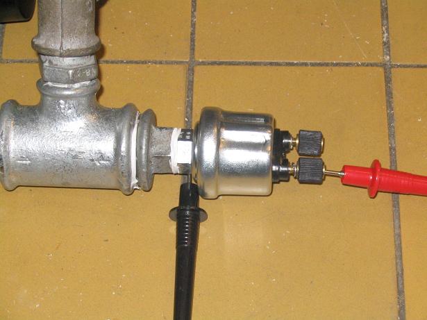
Here you can find a fuel pressure sensor having a gauge and an alarm outlet pin:

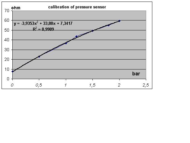
See the calibration test result below.

The alarm sensor part switches on below 0,8 bar. (useful to lit "oil-pressure-too-low" indicator lamp)
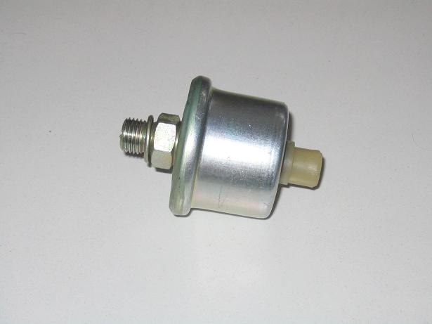
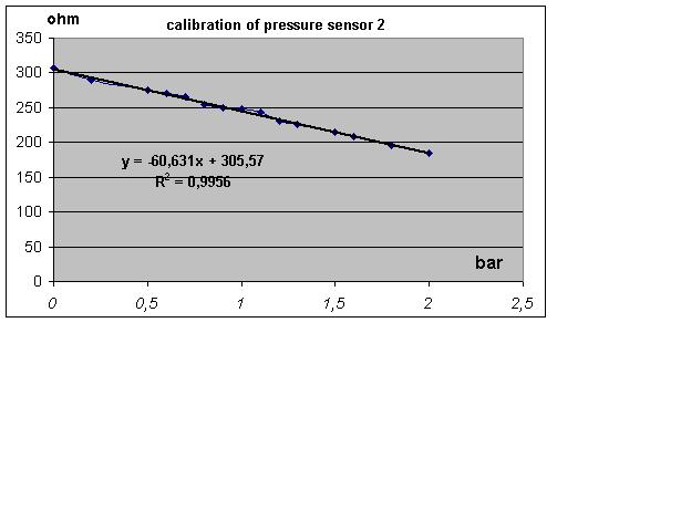
Another type fuelpressure_sensor:

Its calibration curve is linear:

This is not absolute pressure, but relative to athmosperic. So 5bar measurement range means (1 bar athmosphere) + (for example):
- 2 bar boost + 3 bar fuel pressure (above MAP)
- or 1.2 bar boost + 3.8 bar fuel pressure (above MAP)
//Is this a 5 bar operating range pressure sensor?
I have 3.5bar base fuel pressure and 2.5 bar boost...
pnanassy
Fuel pressure sensor connection
- GND - resistive pressure sensor - 270 Ohm pullup - 5V (EC36pin28)
- the signal from the sensor (not the GND but the other end, of course: that has the pullup) connected to an analog input: EC18pin6, 12 or 16 depending on your ECM configuration, see text for assembled controller in WebShop
- 1.0.36 firmware can log the MCP3208 signals (as 0..5V) to MegaTune
- try to take note of the real pressure and real voltage (just for verification) to be compared to the readings in the log
- conversion table (voltage to real pressure) will be added later (don't forget to publish on your project page the type of sensor used!).
- propose a position on the 4x20 LCD for the fuel pressure (maybe instead of the iac RPM target on the bottom right part of mlp00 ? - That would be perfect. FERO)