Engine runs with tec 2 Engine management - should run with GenBoard soon in similar configuration
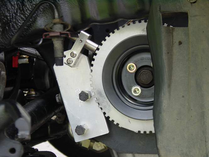
- 60-2 crankwheel with a Magnetic pickup (VR) sensor

3 wire connection of the Magentic pickup:
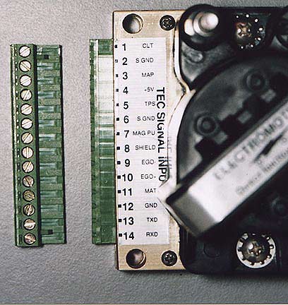
- Mag PU, or VR+ (EC36-pin27) (TEC2 sensor input terminal 7)
- Shield (connected to Ground, see below)
- Ground of both ECMs, or VR- (EC36-pin26) (TEC2 sensor input terminal 6)
It is theoretically OK to run the same signal to both GenBoard and tec 2 since VR- is connected to GND for each (not to 0.7V on one, and 0V on the other, for example).
This way GenBoard should read the signal while the car is running. I'll check RPM and also upload InputTrigger/TriggerLog so others can check too (eg. if VR is not accidentally inverted).
Remember there are 2 options for InputTrigger, HALL or VR. Check that your primarytrigger HW is set for VR (through the LM1815 circuit).
Check operation with OutputTrigger: it is very simple, and only takes a capacitor.
TEC2 input connectors:

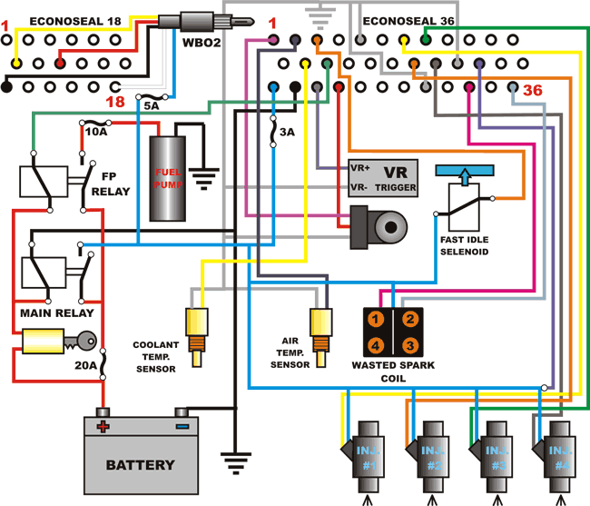
GenBoard wiring harness I'm going to be using - except ground connections that are a bit mix-matched:

And here is my harness made by T3bunny
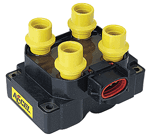
Searched and found a coil pack that should work with the setup i'm trying to do this coil pack has a 3 pins.
- pin #1 is the left side of the pack 1&4.
- Pin #2 is 12v+.
- Pin #3 is the right side of the pack 2&3.

- I'm gonna use a similar coil pack and would like to know where you got the connector fore it? -HansK
- MembersPage/PhatBob - Thats a Ford EDIS coilpack, the connectors seem to be a Ford Dealer part. There are other coil packs out there, like the Sagem packs on Renaults and Citroens which are a similar configuration but use 3 and 4 pin Junior timer connectors.
Trigger position
TDC on tooth11 (if tooth after the missing tooth is tooth0), which means 66 degrees.
- trigger_tooth=01 that is 6 degrees
- ign_tdcdelay=78 (decimal 120 which is 60 degrees)
So that becomes:\nÿ1ÿ
Update
3/10/05 at 5:38p.m I'm happy to say Genboard got a RPM signal from VR sensor.
3/12/05 I got the Genboard hooked up for Injection but the config files for injection won't allow my car to keep running pass 10 seconds. Tried to change setting in MT software but didn't work. Rebuilding Config and tables from TEC2 so it will be acle to keep the car running. I was using Dave Config and tables.
Questions
See HexaDecimal for basic info on hexadecimal numbers. You can use advanced mode of calc (xcalc, whatever appropriate) to verify conversion.
See global.h for meaning and units of variables (unit is very important).
GenBoard/Manual/Config/InjectorOpening related
- injopen=43 (decimal 67) means 1080 usec (since 16 usec unit).But let me warn that injopen depends on flyback, so it is not absolutely valid to transfer values from unknown environment. You likely want 800..1000 usec injopen. For Anything higher, you'll likely end up with very low values in low-kpa bins of the VE table
- Battery voltage correction in (who's?) dave's config is set to 00 but I want to set it to 0.1 (are you aware of the unit?). Check config from MembersPage/MarcellGal/EngineSwap also, injopen is definitely finer than in Dave's config (iac also, but don't copy wbo2 settings because HW is non-standard).
PWM current Limit
- injpwm
- injpwm=80 (128/256) is 50%
- injpwm=4c (77/256) is 30% (which means appr. 14V * 0.3 = 4.2V on injectors during the hold-time). Sounds like a good starting value to me.
- injpwmt=0A means 1.0ms since unit is 100 usec
See GenBoard/Manual/Tables for lambdacorr values.