Changes by last author:
Added:
|
Measurements
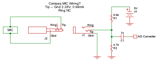
Resistance between pins: (1) - 20ohms - (2) - 20ohms - (3) (So there are 40 ohms between pin 1 and 3) Without connection there's no "default" position. According to BenGTR: "Original" wiring ('0 280 140 509' valve (from E30 -89) is as follows... Pin 2 -> 12V supply. pin 1 -> to Motronic ECU pin 22 (white-green) Pin 3 -> to Motronic ECU pin 4 (white-yellow) I've made measurements to motronic control signals. All measurements done with ignition on but engine is off. I've been seeking long for specs. about notebook's mic. input. I found this:
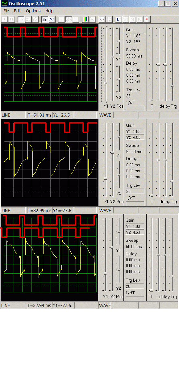
As you might found out I used the (mono!) mic input as a scope. Here are the results:
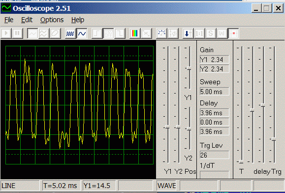
First pic is channel 1 (solenoid pin1), second is channel 2(solenoid pin3). It's quite obvious that the sum of the duty of the two channels is appr 100%. Third image is when both channels connected. How? I used to connect the ground of the notebook and the car, and the signal was connected through 2.1k resistor for one channel and through 10k resistor for the other. (I'm not sure which one is which) * Yellow is the measurement * red is what I guesstimated for the real signal. (Since measured through a series capacitor). Apparently you (for some reason) assume that the notebook input inverts the signal. On the third picture I tried to put them together but not sure that it's the good alignment, unfortunately 10kOhm channel is not so different from the case when both channels is "on" (switched GND). These are my voltage calculations for all of the cases: R2.1k R10k Voltage off off 2.28V off on 1.82V on off 1.02V on on 0.92V Frequency is about 100Hz for sure. I made a measurement to the current GenBoard control too:
It was only the first channel I checked, because it was way too fast to see difference when both were connected. (And not too interesting at all, we know how it's working :) Appr. ~2kHz! Actually it is soft-PWM controlled, which means DC is controlled with high resolution (at high freq); also with small overhead. |


